36
FireLite SLC Wiring Manual — P/N 51309:R3 7/29/2019
Monitor Modules MMF-300 Wiring Diagrams
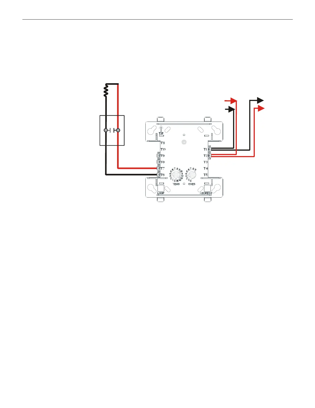
5.3.3 MMF-300 Wiring for Emergency Alarm System Applications
Connect the SLC wiring to the module terminals 1 (–) and 2 (+).
Each module takes one address on the SLC. Use the rotary switches on the module to set it to the required SLC address. Refer to “Setting
an SLC address for a Single Point Module” on page 33.
The figure below shows typical wiring for a supervised and power-limited Emergency Signaling circuit using an MMF-300 module.
• See “Power Considerations” on page 63 for information on supervising 24 VDC power.
• See Section 6, “Control Modules” for instructions on using control modules as NACs on an SLC.
• Refer to the Device Compatibility Document #15384 for compatible smoke detector
s.
47K ELR
(supplied
with module)
SLC
MMF-300 Module
programmed for Tornado,
Hazard, or Medical operation.
Refer to the control panel
installation manual.
IDC
UL-listed Signaling
appliance such as the
Fire-Lite FSS-2400E
SLC-emer.wmf
Figure 5.11 Emergency Signaling Wiring with an MMF-300
 Loading...


