42
FireLite SLC Wiring Manual — P/N 51309:R3 7/29/2019
Monitor Modules MMF-302-6 Wiring Diagrams
5.7 MMF-302-6 Wiring Diagrams
Following are wiring diagrams that concern NFPA Class B and Class A Initiating Device Circuits (IDCs) using MMF-302-6 monitor
modules.
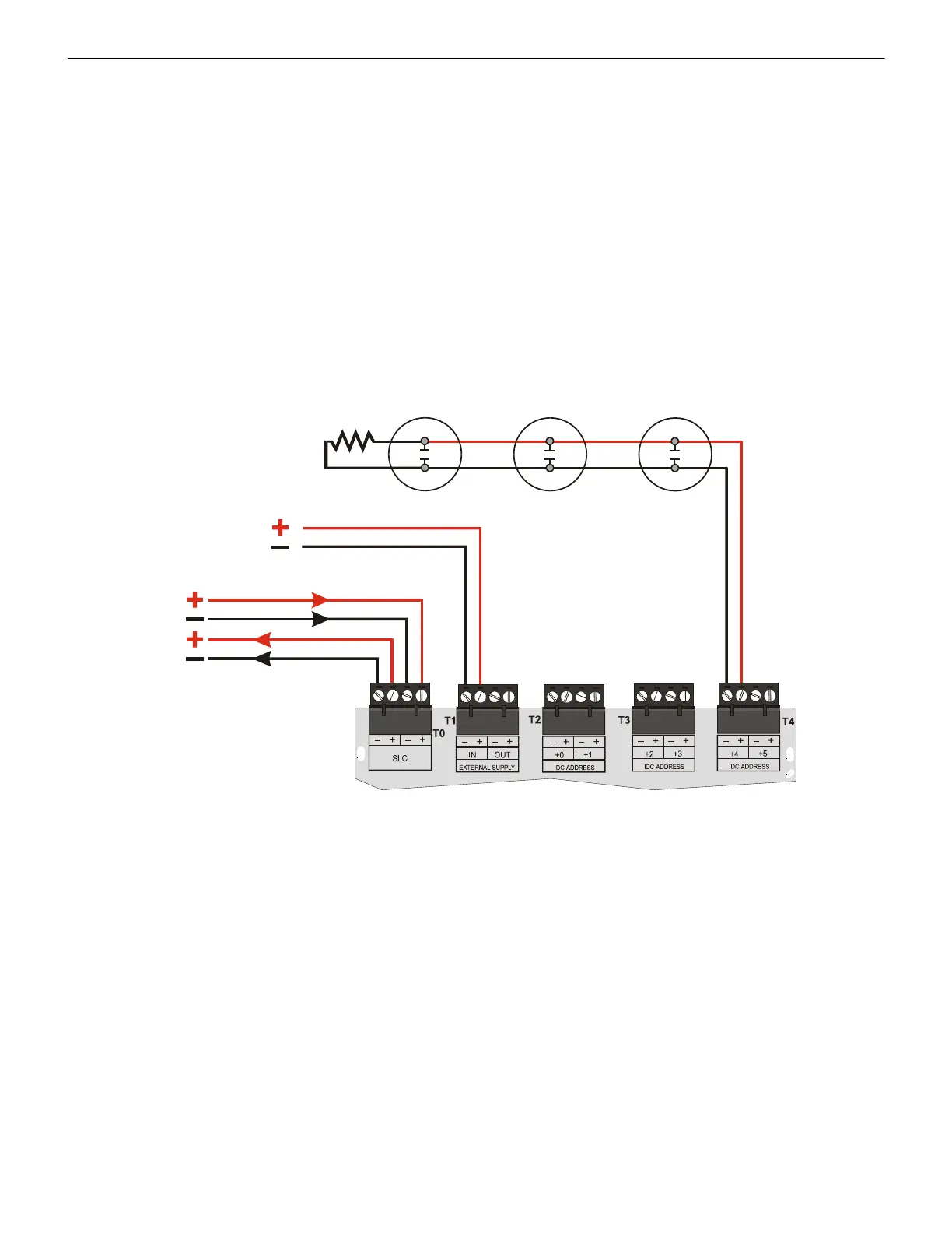
5.7.1 Wiring a NFPA Class B IDC with an MMF-302-6
Connect the SLC wiring to the module terminals T0 as shown below.
Use the rotary switches on the module to set the base SLC address. Each module takes six addresses on the SLC. The remaining module
points are automatically assigned to the next five higher addresses. Refer to “Setting an SLC address for a Multi-Point Module” on page
33.
DO NOT set the lowest address above 150 (41 for the MS-9050UD or ES-50X, 90 for the MS-9200, MS-9200UD, MS-9200UDLS, or
ES-200X), as the other module points will be assigned to nonexistent addresses.
The figure below shows typical wiring for a supervised and power-limited NFPA Class B IDC using an MMF-302-6 module.
• Refer to the Device Compatibility Document for compatible smoke detectors.
• 24 VDC power must be provided from a UL listed power supply for fire protection use. This power is inherently supervised by the
module.
• See “Power Considerations” on page 63 for information on 24 VDC power.
Two-wire smoke detectors
IDC
Out
MMF-302-6
24 VDC resettable power
3.9K ELR
(supplied with
module)
SLC-idcB5.wmf
SLC
Figure 5.17 Typical Class B IDC Wiring with an MMF-302-6
 Loading...


