38
FireLite SLC Wiring Manual — P/N 51309:R3 7/29/2019
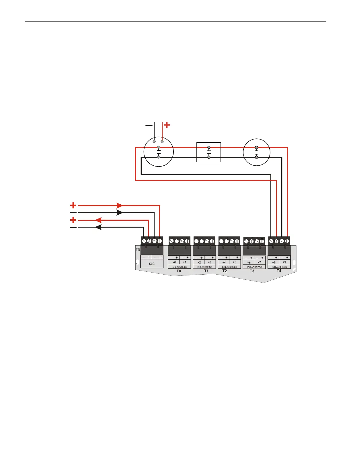
Monitor Modules MMF-300-10 Wiring Diagrams
5.4.2 Wiring a NFPA Class A IDC with an MMF-300-10
Connect the SLC wiring to the module terminals T5 as shown below.
Use the rotary switches on the module to set the base SLC address. Each module takes five alternating addresses on the SLC. The
remaining module points are automatically assigned to the next four higher addresses. (Example: 28, 30, 32, 34 and 36). Refer to “Set-
ting an SLC address for a Multi-Point Module” on page 33.
DO NOT set the lowest address above 150 (41 for the MS-9050UD or ES-50X, 90 for the MS-9200, MS-9200UD, MS-9200UDLS, or
ES-200X), as the other module points will be assigned to nonexistent addresses.
The figure below shows typical wiring for a supervised and power-limited NFPA Class A IDC using an MMF-300-10 module.
• Refer to the Device Compatibility Document for compatible smoke detectors.
• See “Power Considerations” on page 63 for information on supervising 24 VDC power.
24 VDC Power
Filtered, Regulated, Resettable
24 VDC Four-wire
Detector Base
Manual Pull
Station
Heat
Detector
IDC
Out
MMF-300-10
SLC
IDC
Return
SLC-idcD3.cdwmf
Figure 5.13 Typical Class A IDC Wiring with an MMF-300-10
 Loading...


