NFS2-3030 Programming Manual — P/N 52545:K1 03/20/2012 97
NFPA Releasing Applications Releasing Applications
B.2 NFPA Releasing Applications
This control panel can be used for agent release or preaction/deluge control applications. In a
properly configured system with compatible, listed actuating and initiating devices, this control
panel complies with the following NFPA standards for installation in accordance with the
acceptable standard:
Table B.1 NFPA Standards for Releasing Applications
B.3 Abort Switches
The control panel provides for four types of abort switches - ULI, IRI, NYC, and AHJ - each of
which will affect the operation of the delay timer in the releasing zone. For example, an NYC Abort
Switch for releasing zone ZR05 affects only the delay timer in ZR05.
When an initiating device activates, pressi
ng and holding the abort switch will prevent the control
panel from sending the command to dump releasing agents when the Delay Time expires.
Requirements for using an abort switch include
the following:
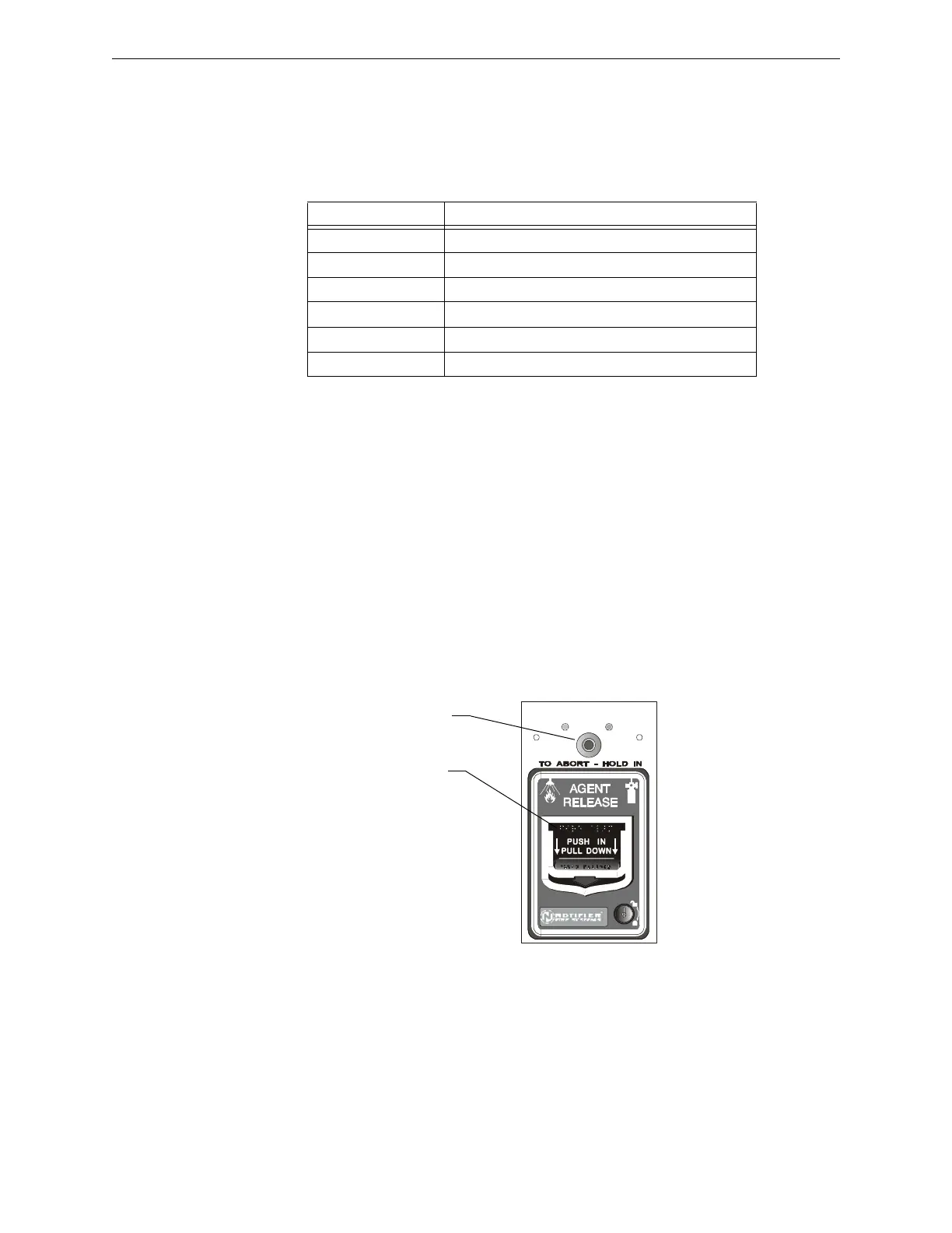
• A monitor module must be connected to a UL-listed abort st
ation, such as the NBG-12LRA
shown below.
• The monitor module must be programmed with the Type Code
ABORT SWITCH.
• An abort switch shall not be used with a preaction system.
Figure B.1 UL-listed Abort Station
This section contains information
o
n each type of abort switch.
Example of an Abort Switch Application
The figure below contains an illustration for an abort switch
application configuration using
releasing zone ZR05 as an example. The configuration includes:
Standard Covers
NFPA 13 Sprinkler Systems
NFPA 15 Water Spray Systems
NFPA 16 Foam-water Deluge and Foam-water Spray Systems
NFPA 17 Dry Chemical Extinguishing Systems
NFPA 17A Wet Chemical Extinguishing Systems
NFPA 2001 Clean Agent Fire Extinguishing Systems
Abort Switch
Manual Agent
Release lever
CTIVATED
NBG-12LRA station with Abort Switch
 Loading...


