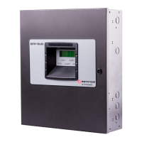
Do you have a question about the Honeywell NOTIFIER SFP-5UD Series and is the answer not in the manual?
| Brand | Honeywell |
|---|---|
| Model | NOTIFIER SFP-5UD Series |
| Category | Control Panel |
| Language | English |
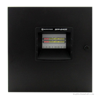
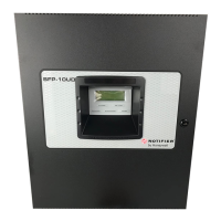
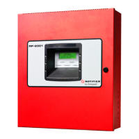
Lists key features of the SFP-5UD/SFP-10UD Fire Alarm Control Panel.
Details AC power, battery, and other technical specifications for the FACP.
Describes the LCD display, key panel, LED indicators, and local piezo sounder.
Explains the functions and capabilities of the built-in DACT.
Details the main circuit board, power supply, cabinet, and batteries.
Lists and briefly describes available optional modules like converters and annunciators.
Covers telephone circuit requirements, digital communicator installation, and warnings.
Provides instructions and precautions for mounting the FACP backbox.
Details AC power and battery connections, including safety warnings.
Explains initiating device circuits (IDCs), including types and configuration options.
Covers Notification Appliance Circuits (NACs), relays, and special application power outputs.
Details the separation and routing of power-limited and nonpower-limited wiring.
Illustrates the wiring and installation of the DACT for telephone line connections.
Guides the installation of optional modules like Class A converters and transmitter modules.
Covers ANN-BUS wiring, device addressing, and installation of annunciators.
Outlines methods for site-specific programming using keypad or PC.
Describes initial programming steps after wiring and applying power.
Explains the navigation and options within the programming interface.
Details the use of factory-set and user-defined passwords for programming access.
Covers programming options available under the Master level, including zones, NACs, and relays.
Describes programming features accessible via the Maintenance level, such as history and walktest.
Explains the functions of the panel's control buttons like Acknowledge, Silence, and Reset.
Describes the meaning of panel LEDs (AC Power, Fire Alarm, etc.) and the piezo sounder.
Details the system's status and functions during normal, non-alarm conditions.
Explains how troubles are indicated and reported on the panel's LCD and system.
Describes how the system behaves and indicates when an alarm condition occurs.
Explains system responses to supervisory events like freeze or tamper conditions.
Details how the system handles process monitor conditions.
Describes the system's behavior for hazard and tornado condition activations.
Explains the system's response to medical alert condition activations.
Covers enabling and disabling input zones and notification appliance circuits.
Describes how waterflow circuits function and interact with panel controls.
Explains detector polling for maintenance, freeze conditions, and alarm verification.
Details the FACP's real-time clock, date, and daylight savings time features.
Lists the available pulse rates for coded operation on NAC circuits.
Explains the presignal option for delaying NAC activation for visual verification.
Describes the PAS feature which delays panel activation for smoke detector alarms.
Covers timers like Silence Inhibit, Autosilence, and Trouble Reminder.
Details how to perform silent or audible walktests and view results.
Explains how to view system status, programming, history, and settings.
Lists the priority order for events transmitted to central stations.
Guides on enabling and performing remote downloads for FACP programming.
Details the process of transferring programs via Service Terminal and security features.
Outlines key security measures for data transfer and access control.
Introduces the steps for calculating power supply and battery requirements.
Details how to determine the required AC branch circuit current for the system.
Explains how to calculate primary and secondary current draws for various conditions.
Guides on calculating required battery capacity based on standby and alarm loads.
Describes the structure of data transmitted using the Ademco Contact ID format.
Shows an example of a typical alarm and trouble report printout from a central station.
Details connecting FACP dry contacts to central/remote station transmitters.
Illustrates the wiring connections between the FACP and a Keltron receiver.
Lists NAC wiring requirements for the SFP-5UD FACP with FLPS-3 power supply.
Lists NAC wiring requirements for SFP-5UDC/SFP-10UD FACP with FLPS-7 power supply.
Provides a table of programming options and their factory default settings.
Details the installation of the N-ANN-LED annunciator for Canadian models.
Outlines the procedure for submitting and handling warranty claims for products.
