SFP-5UD & SFP-10UD Series Manual— P/N 52879:C2 1/24/2012 37
Installation of Optional Modules Installation
2.7 Installation of Optional Modules
2.7.1 N-CAC-5X Class A Converter Module
Installation
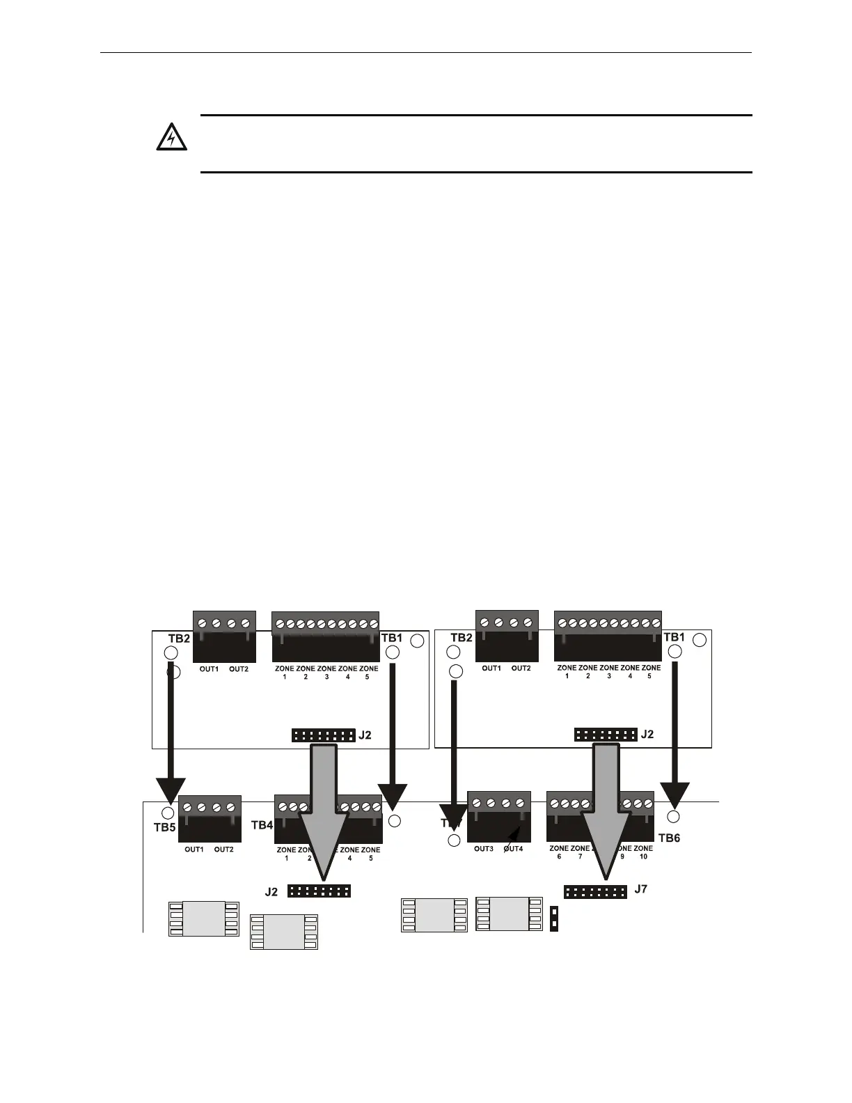
The N-CAC-5X Module can be used to convert five Style B (Class B) Initiating Device Circuits to
Style D (Class A) and the two Style Y (Class B) Notification Appliance Circuits to Style Z (Class
A). The module plugs into connector J2 which is located at the top left of the SFP-5UD and SFP-
10UD main circuit board and J7 which is located at the top center of the SFP-10UD. Note that two
N-CAC-5X modules are required to convert all NACs and IDCs on the SFP-10UD to Class A cir-
cuits.
To install the N-CAC-5X in the SFP-5UD or SFP-10UD, remove the two main circuit board
mounting screws referenced in the following illustration and replace with the two supplied
male/female standoffs in the locations indicated in the following figure. Carefully align the con-
nector on the N-CAC-5X with J2 on the FACP main circuit board and press the module securely
into place. Make certain the pins are properly aligned to prevent bending or breaking of any con-
nector pins. Secure the N-CAC-5X to the standoffs with the screws that were just removed.
To install the second N-CAC-5X on J7 of the SFP-10UD, remove the main circuit board mounting
screw referenced in the following illustration and replace with the supplied male/female standoff.
Insert the supplied plastic standoff in the location indicated in the following illustration. Carefully
align the connector on the N-CAC-5X with J7 and press the module securely into place. Make cer-
tain the pins are properly aligned to prevent bending or breaking of any connector pins. Secure the
N-CAC-5X to the metal standoff with the screw that was just removed.
WARNING: RISK OF ELECTRICAL SHOCK
REMOVE ALL POWER (AC AND DC) BEFORE INSTALLING OR REMOVING MODULES OR
WIRING.
Figure 2.14 N-CAC-5X Module Installation
SFP-10UD Main Circuit Board
Metal
Standoff
Plastic
Standoff
N-CAC-5X Module
ms-10udcac5mnt.wmf
N-CAC-5X Module
Metal
Standoff
Metal
Standoff
Installation in SFP-5UD or SFP-10UD
Installation in SFP-10UD

 Loading...


