32 SFP-5UD & SFP-10UD Series Manual— P/N 52879:C2 1/24/2012
Installation Output Circuits
2.4 Output Circuits
2.4.1 Notification Appliance Circuits
Total current drawn from the four Style Y (Class B) Notification Appliance Circuits as well as other
DC power outputs cannot exceed 3.0 amps for the SFP-5UD [2.5 amp maximum per NAC] pow-
ered by the FLPS-3 power supply or 7.0 amps for the SFP-5UDC, SFP-10UD/E [3.0 amps maxi-
mum per NAC] powered by the FLPS-7 power supply (refer to “Power Supply Calculations” on
page 135). Each circuit is supervised, power-limited and provides special application power. Refer
to the Notifier Device Compatibility Document for a listing of compatible notification appliances.
The NACs can be converted to Style Z (Class A) by installing the optional Class A Converter mod-
ule. Refer to “N-CAC-5X Class A Converter Module” on page 37.
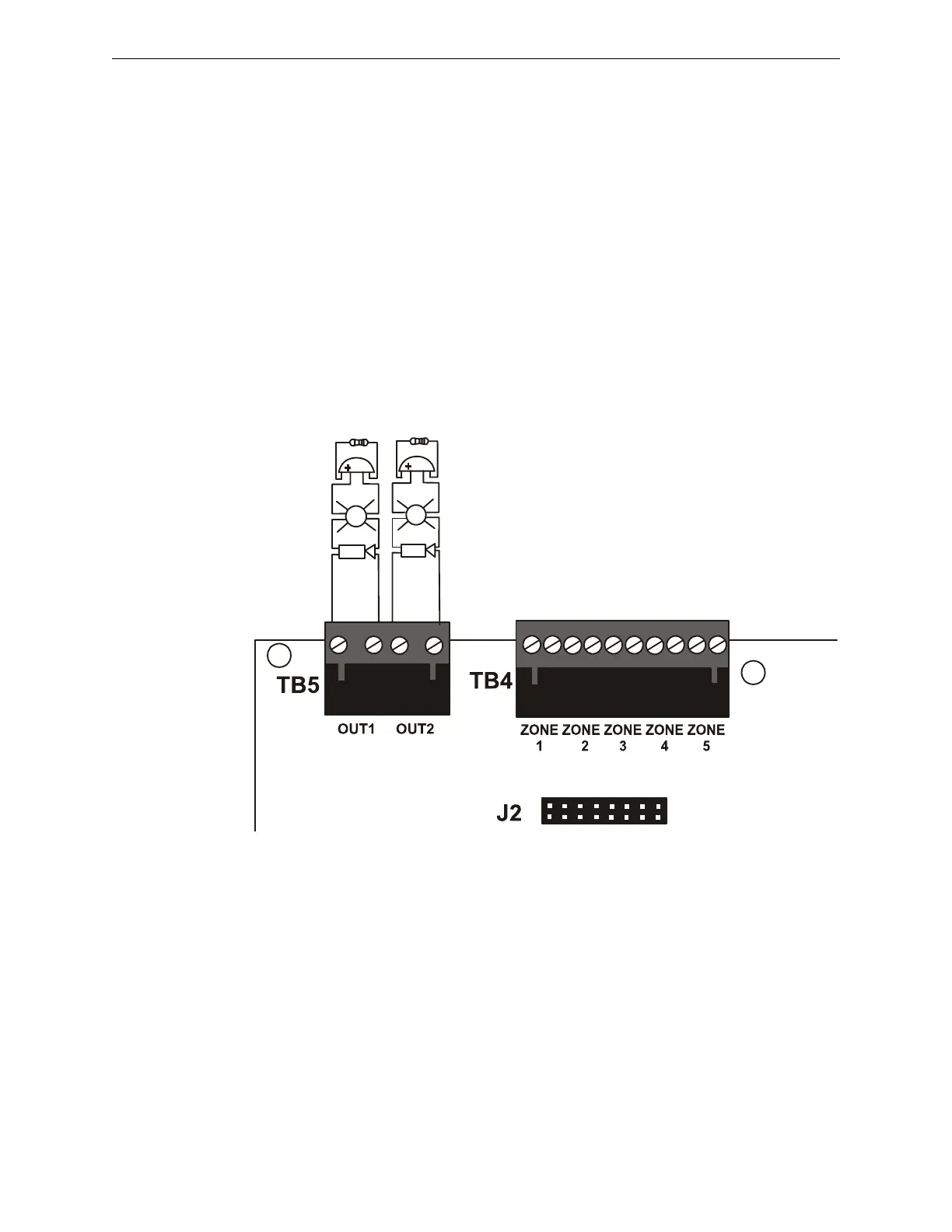
Figure 2.7 NAC Connections
Class B Notification Appliance Circuits (supervised and power-limited)
4.7 K, ½ watt resistor P/N:71252
Dummy load any unused circuits (P/N: 71245)
Polarized Bell
Polarized Strobe
Polarized Horn Polarized Horn
Polarized Horn-Strobe
Polarized Bell
Notification Appliance Circuit
polarity shown in alarm condition
ms-10UDnac.wmf
+ - + -

 Loading...


