OMNI-408/OMNI-408EU Installation and Setup Guide
7–32
In locations L1-L4, enter the digit for the desired system options from the table above. See Figure 6 for
keyfob buttons.
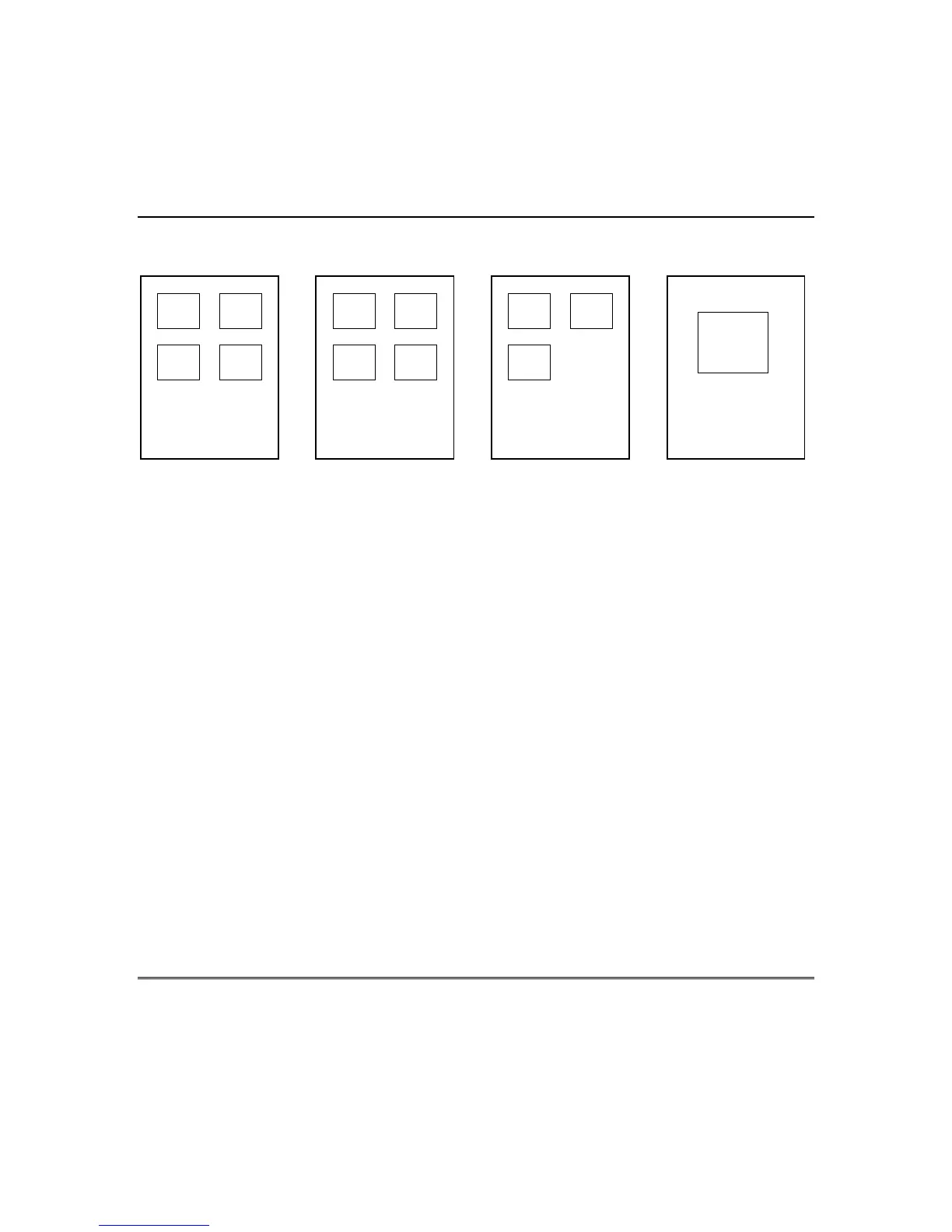
Figure 6. Keyfob Buttons
QUESTION 36
RF REMOTE KEYFOB 6 BUTTON DEFINITIONS DEFAULT = 0000
Question 36, L1 - RF Remote Keyfob 6 Button 1 Default = 0
Question 36, L2 - RF Remote Keyfob 6 Button 2 Default = 0
Question 36, L3 - RF Remote Keyfob 6 Button 3 Default = 0
Question 36, L4 - RF Remote Keyfob 6 Button 4 Default = 0
In locations L1-L4, enter the digit for the desired system options from the table above. See Figure 6 for
keyfob buttons.
QUESTION 37
TRIGGERS 1 & 2 DEFAULT = 0003
The control panel contains 2 voltage level output triggers. Triggers 1 and 2 are selected in this
question. To select a trigger type, enter in either L1 and L2 or L3 and L4 the 2 digits representing the
desired trigger type for each output trigger. Certain triggers can be selected as Noninverting or
Inverting (see description below). Consult the table below to determine the trigger types available.
Question 37, L1 & L2 - Define Trigger #1 Default = 00
Question 37, L3 & L4 - Define Trigger #2 Default = 03
NOTE: If the trigger is unused, enter “00.”
3 2
4 1
5804 KEYFOB
3 2
4 1
5801 KEYFOB
3 2
1
5803 KEYFOB 5802MN KEYFOB
1
 Loading...


