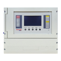
Control Panel Installation
P/N 151204 3-11
3.9 Terminal Strip Description
The terminal strips on the PC board are non-removable. Table 3-4 lists the functions of each
terminal. See Section 3.4 for the board layout.
Table 3-4: Terminal Descriptions
Function
Terminal
Number
Terminal Label Comments
Zone 1 input.
1A
Z1
Zone 1 input Class A (Style D) or Class B (Style B). See
Section 3.11 for wiring configurations.
2B
3C
4D
Zone 2 input
5A
Z2
Zone 2 input Class A (Style D) or Class B (Style B). See
Section 3.11 for wiring configurations.
6B
7C
8D
Ground 9 GND
Zone 3 input 10 Z3 Zone input Class B (Style B). Refer to Section 3.11.2.
Power Limited at 100mA. Voltage 27.4 VDC.
Power (Zone 3 & 4) 11 PWR
Zone 4 input 12 Z4
Zone 5 input 13 Z5
Smoke Power 14 PWR
Zone 6 input 15 Z6
Zone 7 input 16 Z7
Smoke Power 17 PWR
Zone 8 input 18 Z8
Zone9 input 19 Z9
Smoke Power 20 PWR
Zone 10 input 21 Z10
Ground 22 GND
AC Power Connections
23 B
24 Earth
25 W
SBUS Connections
26 GND Used to connect SK-5217 Zone Expanders and 5280
Status Display Modules to the control panel. Accessory
Power (terminals 26 and 27) provides 1 Amp total
current.
27 +24DC
28 A
29 B
Remote Annunciator
Connections
30 SKI Used to connect 5235 remote annunciators to the control
panel.
31 SKO
32 PWR
33 GND

 Loading...