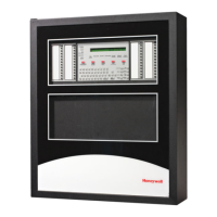
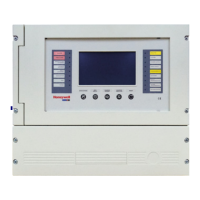
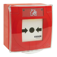
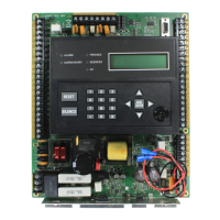
Model SK-5208 Fire Control/Communicator Installation and Operation Manual
3-20 P/N 151204
3.14 Accessory Devices
The section describes how to install the SK-5235 Remote Annunciator, SK-5217 Zone
Expander, the 5824 Serial/Parallel Printer Module, and the SK-5280 Status Display Module.
All circuits are 24 VDC regulated.
All S-Bus devices are Style 1 Class B as per NFPA 72.
3.14.1 Setting ID Codes
Before installing the SK-5235, SK-5217, 5824 or SK-5280, you must first set their
identification codes. Each device must be given its own identification code. For example:
each SK-5235 needs a unique ID code, but a SK-5235 can have the same ID code as a
SK-5217. Each type of device has it’s own device type programmed into it enabling the
control panel to distinguish between the different devices.
On the back of each device is a small 4-position dip switch used to set the ID code. Use the
chart below to determine the dip switch positions for each possible ID code.
Table 3-5: ID Dip Switch Settings
ID Number
Switches
1
1234
0
2
Down Down Down Down
1 Up Down Down Down
2 Down Up Down Down
3 Up Up Down Down
4 Down Down Up Down
5 Up Down Up Down
6 Down Up Up Down
7
Not used
3
8
1.
Switch Settings: Up = On Down = Off
2. Not supervised.
3. ID number 7 and 8 are not valid ID settings.
 Loading...
