Control Panel Installation
P/N 151204 3-27
3.14.3.2 Wiring Relays
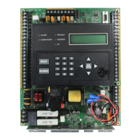
The four on-board relays can be triggered by the active low outputs. For example, the alarm
outputs can all be wired to relay 3 and the trouble outputs can be wired to relay 4
(see Figure 3-17).
C1 is the coil for the relay 1, C2 is the coil for relay 2, C3 and C4 are the coils for relays 3 and
4 respectively.
Figure 3-17 Relay Wiring on the SK-5280
Note: Figure 3-17 uses A7 and T7 to activate relays 3 and 4 as an example. However, any of the outputs can be
used to trip any of the relays.
3.14.3.3 Wiring LEDs to Outputs
The outputs (A1-A10 and T1-T10) can be used to operate LEDs used in a remote annunciator
(see Figure 3-18). Outputs A1-A10 are alarm outputs for the zones corresponding to those
outputs. For example, if the SK-5280 is programmed to output for zones 11-20, then outputs
A1-A10 will correspond with zones 11 through 20.
Outputs T1-T10 are trouble outputs for the zones corresponding to those outputs. for example,
if the SK-5280 is programmed to output for zones 21-30, then outputs T1-T10 will correspond
Relay Rating
2.5A @ 30 VDC/120 VAC
 Loading...
