EasyManua.ls Logo

Honeywell TR50 - User Manual

Honeywell TR50
86 pages
Print Icon
To Next Page IconTo Next Page
Loading...
User Guide
Indoor Air Quality Sensor
TR50

Table of Contents

Questions and Answers

  • S
    Stephanie VargasAug 18, 2025
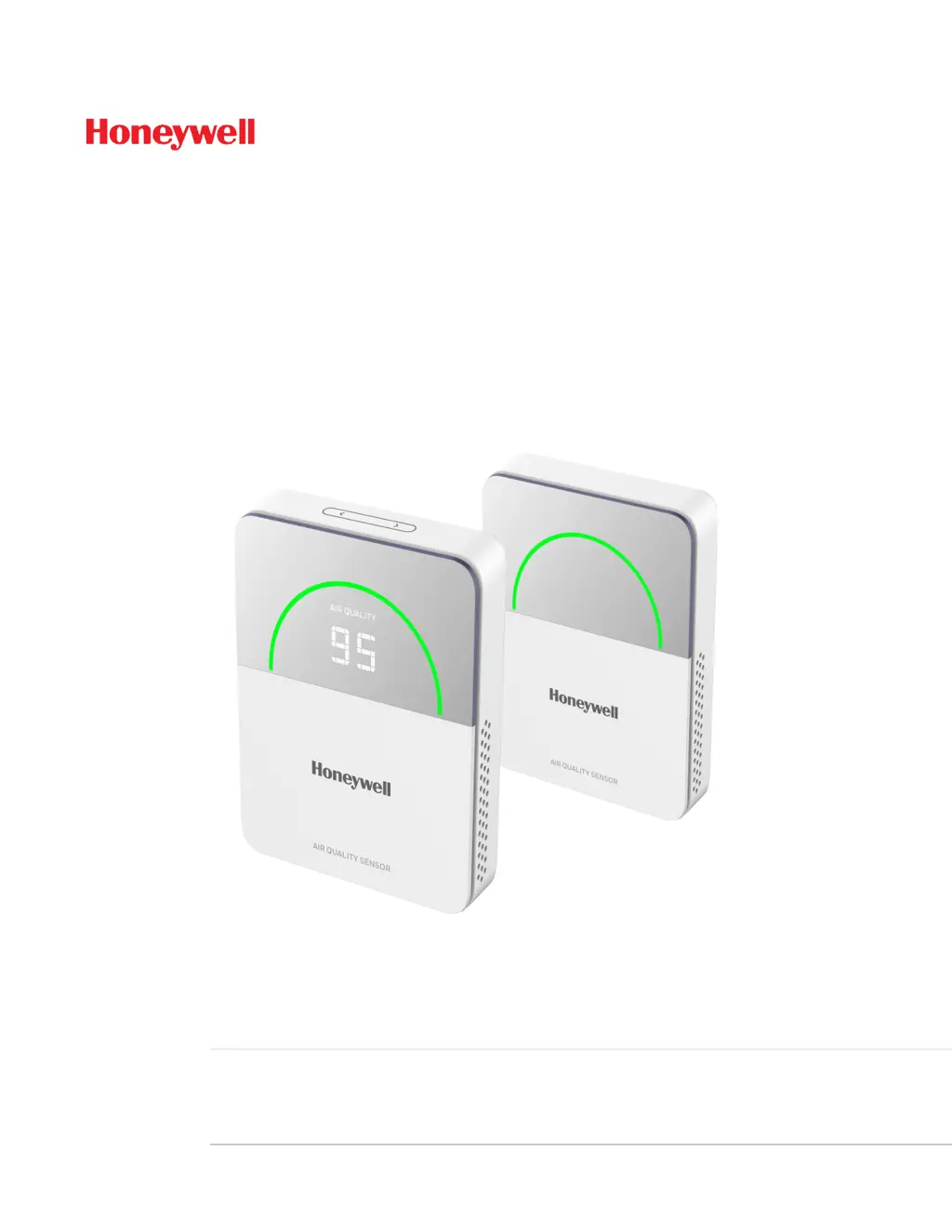
    What to do if Honeywell Security Sensors' CO data is too high or low?
    • N
      nancygutierrezAug 18, 2025
      The CO sensor features a self-calibration function that typically restores CO values to normal levels. To enable self-calibration, ensure the CO concentration remains around 400 ppm for at least 4 hours within every 24-hour period, and maintain this environment for one week.
  • T
    Tim JonesAug 21, 2025
    What to do if Honeywell Security Sensors temperature and humidity value does not change for a long time?
    • J
      Jenna YoungAug 21, 2025
      Try powering the sensor off and then back on to see if the reading returns to a normal value. If this doesn't resolve the issue, the sensor value may not be recoverable.
  • J
    Jeanette SuttonAug 22, 2025
    Why is my Honeywell Security Sensors LCD not displaying any information?
    • S
      Shelby VasquezAug 23, 2025
      Verify that the power supply is working correctly and that the device SKU supports LCD display modes.
  • G
    Gabriel PalmerAug 26, 2025
    What causes communication interruption RS-485 (MODBUS RTU) in Honeywell Security Sensors?
    • S
      smithbenjaminAug 26, 2025
      Check the following: ensure the power supply is stable and the RS-485 terminal is securely connected. Also, verify that the RS-485 communication line hasn't been cut. Finally, check for any nearby inductive loads, such as a water pump, that might be causing electromagnetic interference.
  • H
    Henry BarkerAug 27, 2025
    What should I do if my Honeywell Security Sensors TVOC's deviation is too large (high or low)?
    • M
      Mr. Craig SantosAug 27, 2025
      After powering on the sensor, allow the TVOC levels in the environment to stabilize for at least 48 hours. Initial TVOC data may fluctuate significantly. For faster stabilization, place the equipment outdoors in clear air for at least 24 hours to allow TVOC to retrace its baseline.
  • S
    storresAug 29, 2025
    What to check if Honeywell Security Sensors' RS-485/SylkTM Bus communication is abnormal?
    • R
      ramirezteresaAug 30, 2025
      Ensure the slide switch is in the correct position and that the DIP switch protocol is also set correctly.
  • C
    Colleen Green DVMSep 1, 2025
    What to do if Honeywell Security Sensors temperature and humidity deviation is too large?
    • T
      Troy JonesSep 1, 2025
      Examine the surrounding environmental factors for any influences on the IAQ Sensor. These may include direct sunlight or proximity to heating or air conditioning air outlets.
  • R
    Rachel KelleySep 3, 2025
    What to do if Honeywell Security Sensors PM1.0, PM2.5, and PM10 data are abnormal?
    • S
      Sarah TaylorSep 3, 2025
      Inspect the sensor housing and the air inlet and outlet for any obstructions caused by debris or dust.
  • J
    Jack PowellSep 5, 2025
    Why Honeywell Security Sensors LED ring is dark?
    • V
      Veronica JamesSep 5, 2025
      Verify that the power supply is providing adequate power.
  • R
    Ronnie ShawSep 8, 2025
    What to check if Honeywell Security Sensors touch button has no any feedback?
    • J
      Justin MartinezSep 8, 2025
      Ensure that the touch area is clean and dry. Also, make sure your finger is dry and free from any electrostatic discharge (ESD) risk.

Summary

Introduction to TR50

Introduction

Overview of the TR50 IAQ Sensor, its parameters, and communication protocols.

Dimensions

Physical dimensions of the TR50 IAQ Sensor in inches and millimeters.

Intended Audience and Assumed Knowledge

Details on who the user guide is for and the prerequisite knowledge required.

Specification

Technical specifications including detection parameters, power, and environmental ratings.

System Architecture

Illustrates flexible integration methods of the TR50 IAQ Sensor into a BMS.

Ordering Information

Table detailing part numbers, sensors, communication protocols, display, and power.

Installation

Important Safety Information and Installation Precautions

Crucial safety guidelines and precautions for installing the TR50 IAQ Sensor.

Before Installation

Pre-installation checks and recommendations for a successful setup.

Restricting Access to Network

Measures to prevent unauthorized access to the sensor's network.

Steps to Install TR50 Sensor

Step-by-step instructions for physically installing the TR50 IAQ Sensor.

Wiring Connections

Details on connecting the TR50 IAQ Sensor via RS-485, BACnet, Modbus, and Sylk™ Bus.

Power Up the Sensor Device

Instructions on how to power up the TR50 IAQ Sensor after installation.

Getting Started

Home Screen - User Interface

Description of the TR50 IAQ Sensor's user interface elements.

Touch Button

Functionality and operation of the touch button for parameter navigation.

LED Ring Behavior; Indication

Explanation of LED ring colors and their meanings for air quality and sensor status.

Parameter Description

Overview of the 5 different parameter readings displayed on the TR50 IAQ Sensor.

Mono Display

How the mono segment display shows sensor parameter values.

Display Parameter

Configuration of display modes: Auto Mode and Manual Mode.

Configuration

Topologies Used to Connect TR50 IAQ Sensor

Discusses various flexible ways to integrate the TR50 IAQ Sensor into a BMS.

Dip Switch Configuration

Configuration of dip switches for communication protocols and MAC addresses.

BACnet Mode

Configuration steps for operating the TR50 in BACnet network mode.

Modbus Mode

Configuration steps for operating the TR50 in Modbus network mode.

Slyk Bus Mode

Configuration steps for operating the TR50 in Sylk™ Bus network mode.

RS-485 Configuration

Prerequisites for configuring the RS-485 connection for the TR50 device.

BACnet Configuration

Detailed configuration settings for BACnet communication.

Modbus Configuration

Configuration settings for Modbus communication, including baud rate and port.

Configure TR50 Modbus Device via Niagara

Steps to configure the TR50 Modbus device using the Niagara platform.

Configure TR50 Sylk device via Niagara

Steps to configure the TR50 Sylk device using the Niagara platform.

Configure TR50 Sylk device via CPO

Steps to configure the TR50 Sylk device using the CPO studio.

Operations

About Status LED Ring

Explanation of the LED status ring colors and their meanings for TR50 device.

TVOC Sensor Reading

Information on TVOC sensor stabilization time and data effectiveness.

PM 1 and PM 10 Sensor Reading

Details on PM1 and PM10 sensor measurement channels.

Temperature Unit Change

How to change temperature units from °F to °C using the touch button.

Factory Reset

Procedure for performing a factory reset on the TR50 IAQ Sensor device.

Firmware Download of TR50 via Niagara

Steps to download TR50 firmware using Niagara on plant controllers.

Firmware Download of TR50 (Unitary controller)

Steps to download TR50 firmware on unitary controllers via BACnet.

Firmware Download of TR50 via CPO (Modbus, BACnet and Sylk)

Firmware download procedures for TR50 using CPO tool.

Correction and Calibration

Sensor Offset

Functionality for fine-tuning sensor readings with offset configuration items.

Temperature and Humidity Standard

Information on temperature and humidity sensor calibration and correction.

CO2 Calibration Standard

Details on CO2 sensor calibration features like FRC and ASC.

TVOC Calibration Standard (According to Ethanol Volatilization)

Calibration standard for TVOC sensor based on ethanol volatilization.

PM1.0, PM2.5, and PM10 Calibration Standard (According to GRIMM Technology)

Calibration standard for PM sensors based on GRIMM Technology.

Maintenance and Troubleshooting

Maintenance

Guidelines for regular maintenance of the TR50 IAQ Sensor.

Troubleshooting

Table providing fault conditions and corresponding troubleshooting steps.

Error Code

Information on error codes displayed on the TR50 IAQ Sensor.

Error Code With Display

Explanation of error codes shown on the display for sensor failures.

Error Code Without Display

How error codes are indicated via LED ring for models without display.

Certification and Regulation

Waste Electrical and Electronic Equipment (WEEE)

Disposal guidelines for the TR50 IAQ Sensor at the end of its product life.

FCC Part 15 Compliant

Compliance statement for FCC Part 15 rules regarding device operation.

Power Supply Guidelines and Requirements

Guidelines and requirements for powering the TR50 IAQ Sensor.

Standards and Compliances

List of standards and compliances met by the TR50 IAQ Sensor.

Honeywell TR50 Specifications

General IconGeneral
CategorySecurity Sensors
TypeTemperature and Humidity Sensor
Humidity Range0% to 95% RH (non-condensing)
Accuracy±0.5 °C
Operating Temperature Range-40°C to 70°C (-40°F to 158°F)

Related product manuals