TR50 - User Guide 9
2.3 Wiring Connections
For wiring details of RS-485 via communication BACnet, Modbus and Sylk
TM
Bus
through plant or unitary controller refer hard copy of the latest Mounting
Instructions (31-00566M-02).
2.3.1 Sylk
TM
Bus Wiring
a
For Spyders, use the Resource Usage View in the Spyder Tool to determine
maximum number of devices. For Comfort-Point
TM
Open controllers, there is a
maximum power consumption 1.6 W
Note: When the Sylk
TM
Bus
load is above 1 W, the interval report time must be specified
carefully.
b
As a rule of thumb, single twisted pair (2 wires per cable only), thicker gauge, non-
shielded cable yields best results for longer runs.
c The 30 m distance for standard thermostat wire is conservative, but meant to
reduce the impact of any sources of electrical noise (including but no limited
VFDs, electronic ballasts, etc). Shielded cable recommended only if there is a
need to reduce the effect of electrical noise.
d
These distances also apply for shielded twisted pair.
2.2 Power Up the Sensor Device
Once the TR50 IAQ Sensor device is installed and powered, the device gets started
and shows firmware version number “x.x.x.x” as per the latest updated firmware
and the parameter values are displayed on the LCD.
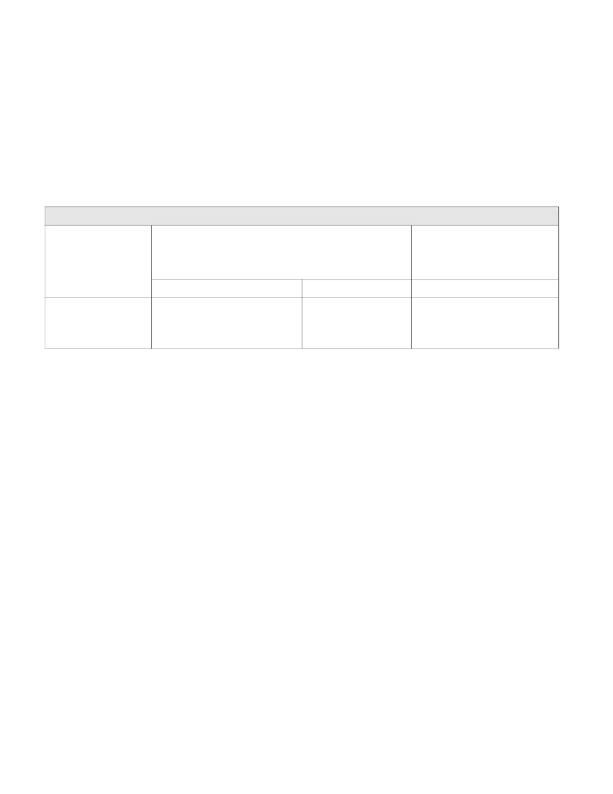
Recommended maximum distance from controller to any Slyk device
Quality and type of
device
a
Single twisted pair, non-shielded, stranded or solid
b
Standard thermostat wire,
(non-twisted), shielded or
non-shielded, stranded or
solid
c,d
18-22 AWG 24 AWG 18-24 AWG
TR50-5D 1.5 W
TR50-5N 1.4 W
TR50-3D 0.9 W
TR50-3N 0.8 W
500 ft (150 m) 400 ft (120 m) 100 ft (30 m)

 Loading...