FAASTFLEX FAAST FLEX Product Guide
www.xtralis.com 15
4 Wiring Installation
4.1 Wiring Considerations
1. All wiring must comply with local requirements and regulations.
2. Panel wiring must comply with the recommendations of the panel manufacturer.
3. Always use appropriate gauge wire. Inspect all connections to ensure they are tight and secure.
4. Remove the cover as shown in Figure3-4.
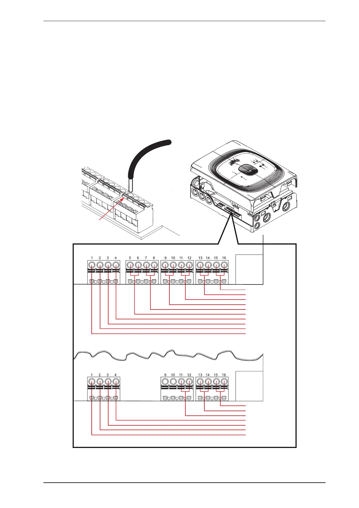
5. Electrical connections are made to the terminal blocks as shown in 4.2. Wire insulation should be
stripped approximately 5mm from the end. Using a small screwdriver, push down on the small tab on the
terminal block, and then insert the wire into the corresponding hole.
Note: Wiring diagrams are printed on the internal covers of the detector.
ALARM CH1
ACTION CH1
FAULT CH1
GPI
GPI
INPUT VOLTAGE -
INPUT VOLTAGE +
SINGLE
CHANNEL
MODEL
ALARM CH1
ACTION CH1
FAULT CH1
ALARM CH2
ACTION CH 2
FAULT CH2
GPI
GPI
INPUT VOLTAGE -
INPUT VOLTAGE +
DUAL
CHANNEL
MODEL
INSERT
WIRE
PRESS DOWN
ON TAB
Figure4-1: Wiring Connections
 Loading...