11
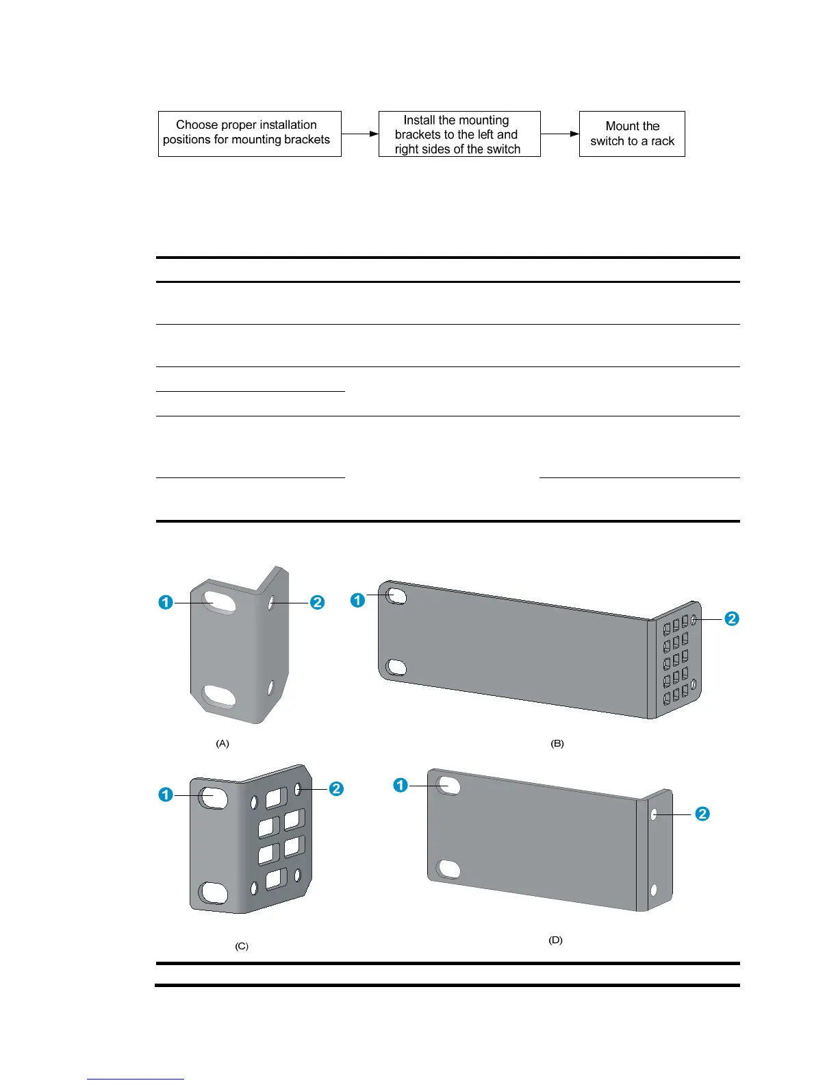
Figure 18 Rack-mounting procedure
Mounting brackets and mounting positions
Table 5 Mounting brackets and positions for the HP 1910 switches
Chassis Bracket vie
osition
• V1910-16G
• V1910-24G
See callout A in Figure 19.
• Front mounting (see Figure 20)
• Rear mounting (see Figure 21)
1910-8G See callout B in Figure 19.
• Front mounting (see Figure 22)
• Rear mounting (see Figure 23)
1910-8G-PoE+ (65W)
See callout D in Figure 19.
• Front mounting (see Figure 24)
• Rear mounting (see Figure 25))
1910-8G-PoE+ (180W)
• V1910-24G-PoE (170W)
• V1910-24G-PoE (365W)
See callout C in Figure 19.
• Front mounting (see Figure 26)
• Mid-mounting (see Figure 27)
• Rear mounting (see Figure 28)
V1910-48G
• Front mounting (see Figure 26)
• Rear mounting (see Figure 28)
Figure 19 Mounting brackets
(1) Holes for attaching to a rack (by using M6 screws)

 Loading...