18
1.
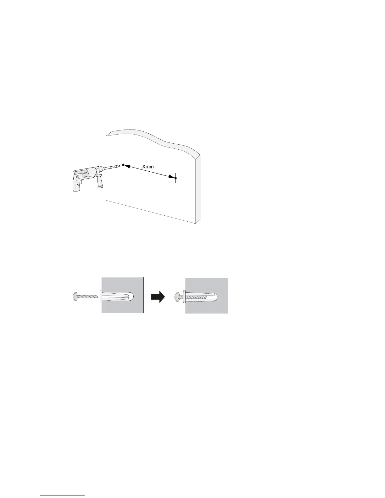
As shown in Figure 34, drill two holes at the same height and make sure that the spacing in
between is as follows:
{ 1910 -8G—98.5 mm (3.88 in)
{ 1910 -8G-PoE+ (65W )—174.0 mm (6.85 in)
{ 1910 -8G-PoE+ (180W )—174.0 mm (6.85 in)
The hole depth and size depends on the anchors and screws you use. Make sure that you can push
the anchors to their full depth in the holes, with their outer edges having a close contact with the
wall, and tightly fasten the screws to the wall.
Figure 34 Spacing between the mounting holes
2. Insert one anchor into each hole until the anchors are flush with the wall surface. See Figure 35.
3. Drive one screw into each wall anchor, leaving at least 1.5 mm (0.06 in) of clearance between the
base of the screw head and the anchor so that the switch can hang on the screws securely.
Figure 35 Install a wall anchor
4. Align the two mounting holes in the switch chassis bottom with the two screws and hang the switch
(see Figure 36). Mak
e sure that the Ethernet ports are facing downwards and the chassis side
panels are perpendicular to the ground.

 Loading...