349
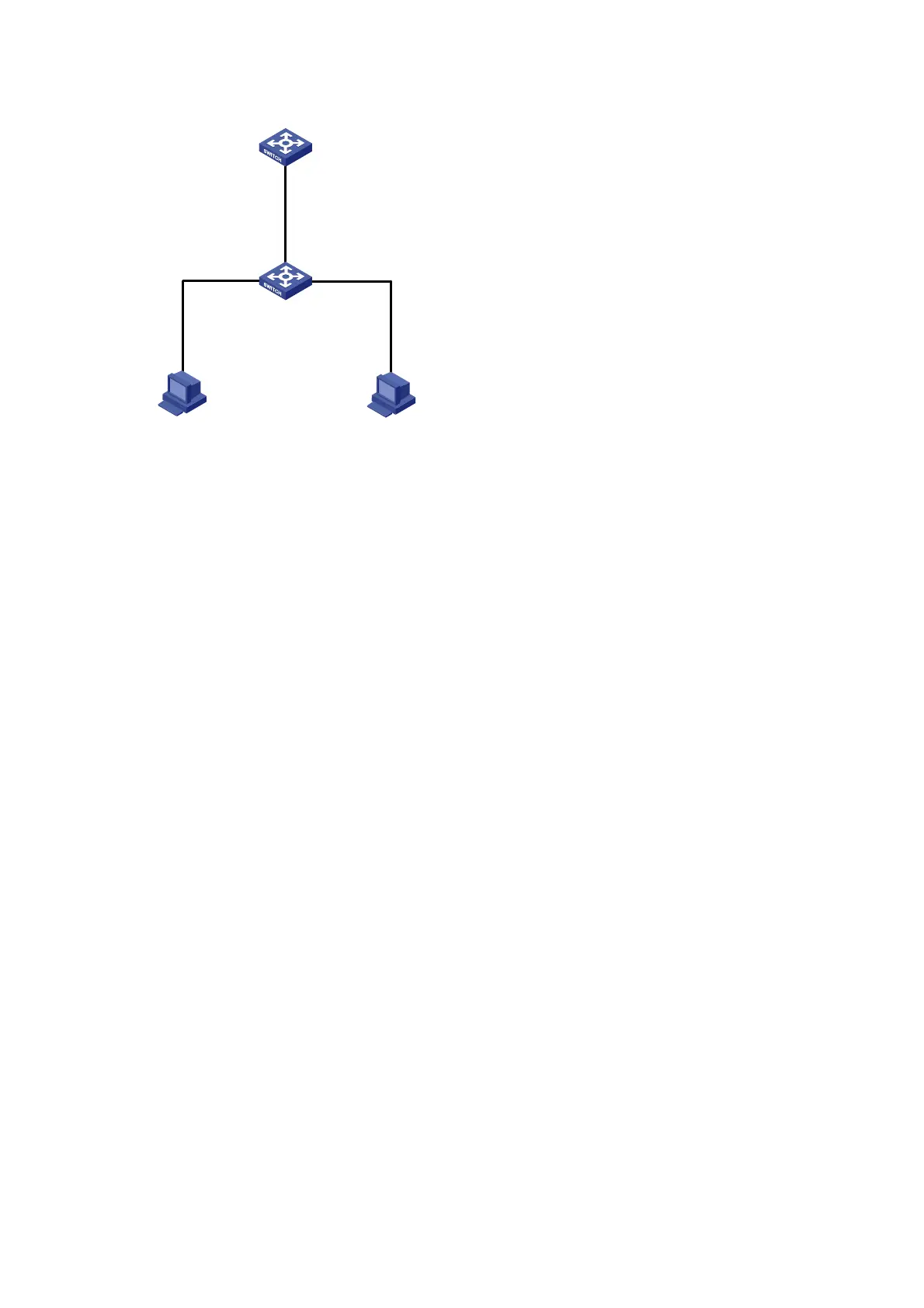
Figure 132 Network diagram
Switch A
Switch B
Host A Host B
Eth1/0/1
Eth1/0/3
Eth1/0/2
Configuration procedure
# Configure ARP filtering on Switch B.
<SwitchB> system-view
[SwitchB] interface ethernet 1/0/1
[SwitchB-Ethernet1/0/1] arp filter binding 10.1.1.2 000f-e349-1233
[SwitchB-Ethernet1/0/1] quit
[SwitchB] interface ethernet 1/0/2
[SwitchB-Ethernet1/0/2] arp filter binding 10.1.1.3 000f-e349-1234
After the configuration is complete, Ethernet 1/0/1 will permit incoming ARP packets with sender IP and
MAC addresses as 10.1.1.2 and 000f-e349-1233, and discard other ARP packets. Ethernet 1/0/2 will
permit incoming ARP packets with sender IP and MAC addresses as 10.1.1.9 and 000f-e349-1233 and
discard other ARP packets. ARP packets from Host A are permitted, but those from Host B are discarded.

 Loading...


