353
ND detection configuration example
Network requirements
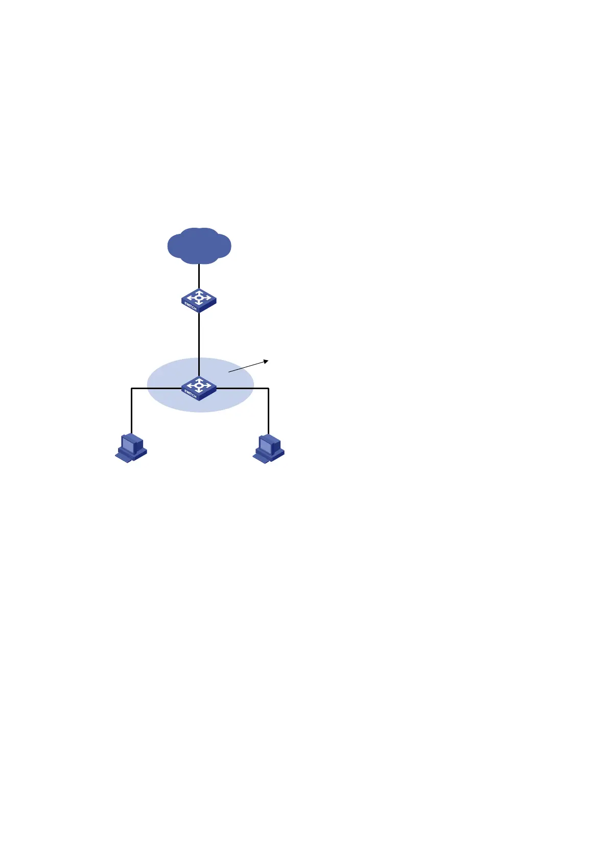
As shown in Figure 134, Host A and Host B connect to Switch A, the gateway, through Switch B. Host A
has the IPv6 address 10::5 and MAC address 0001-0203-0405. Host B has the IPv6 address 10::6 and
MAC address 0001-0203-0607.
Enable ND detection on Switch B to filter out forged ND packets.
Network diagram
Figure 134 Network diagram
Switch A
Switch B
Host A Host B
Eth1/0/3
Vlan-int10
10::1
Gateway
Eth1/0/1
Eth1/0/3
Eth1/0/2
VLAN 10
ND snooping
10::6
0001-0203-0607
10::5
0001-0203-0405
Internet
Configuration procedure
1. Configuring Switch A
# Enable IPv6 forwarding.
<SwitchA> system-view
[SwitchA] ipv6
# Create VLAN 10.
[SwitchA] vlan 10
[SwitchA-vlan10] quit
# Assign port Ethernet 1/0/3 to VLAN 10.
[SwitchA] interface ethernet 1/0/3
[SwitchA- Ethernet1/0/3] port link-type trunk
[SwitchA- Ethernet1/0/3] port trunk permit vlan 10
[SwitchA- Ethernet1/0/3] quit
# Assign an IPv6 address to VLAN-interface 10.
[SwitchA] interface vlan-interface 10

 Loading...


