4
5120-24G EI panel views
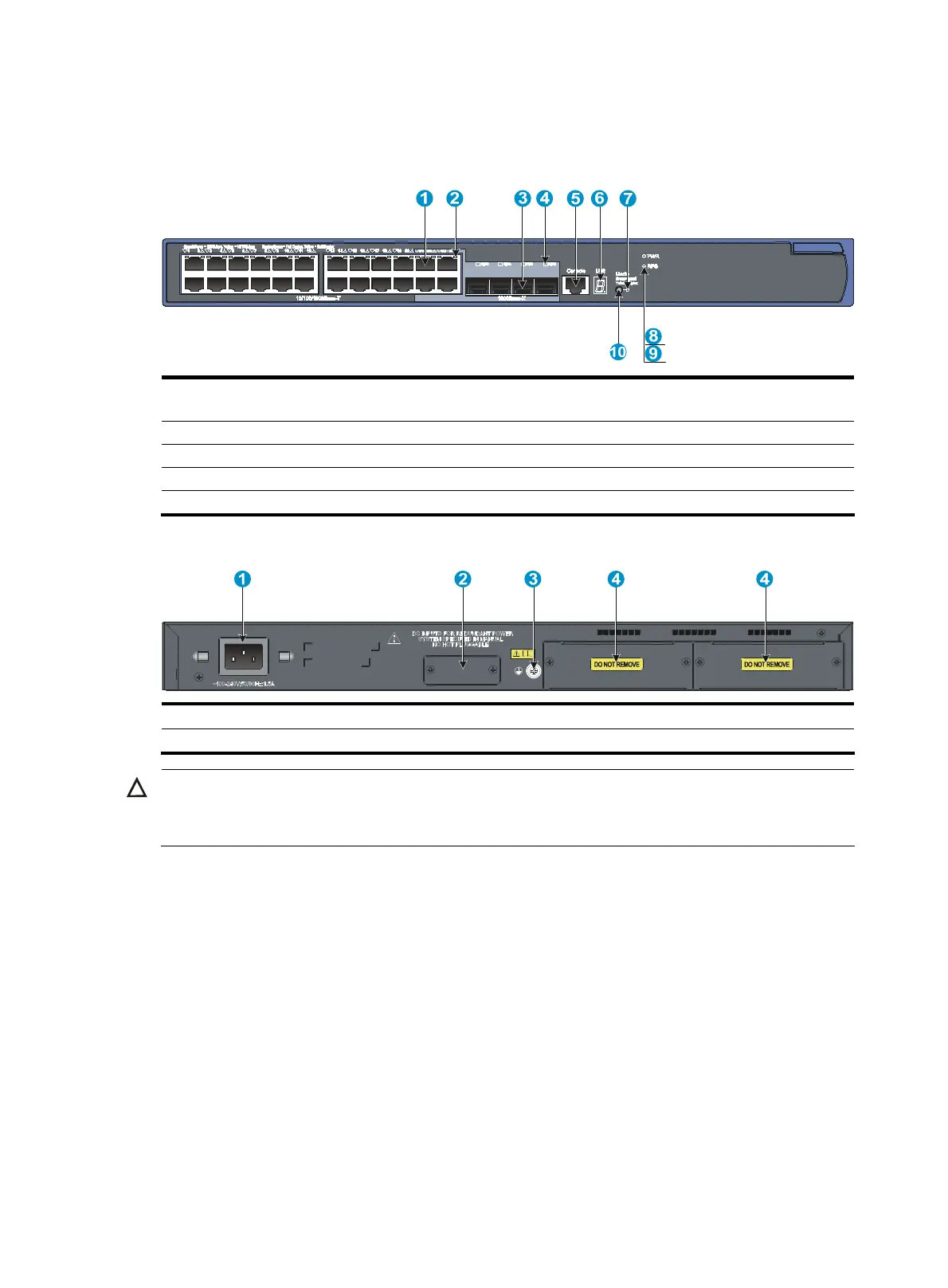
Figure 5 Front panel
(1) 10/100/1000Base-T auto-sensing Ethernet
port
(2) 10/100/1000Base-T Ethernet port LED
(3) SFP port (4) SFP port LED
(5) Console port (6) Seven-segment LED (Unit)
(7) Port mode LED (Mode) (8) System status LED (PWR)
(9) RPS status LED (RPS) (10) Port LED mode switching button
Figure 6 Rear panel
(1) AC-input power receptacle (2) RPS receptacle
(3) Grounding screw (4) “DO NOT REMOVE” label
CAUTION:
The 5120-24G EI switch does not support interface cards.
To ensure
ood ventilation, do not remove the
interface card slot filler panels.

 Loading...


