Chapter 3 Replacing Assemblies
To Remove A3 1.5/3.0/5.0/12.4 GHz Channel Assembly (Option
015/030/050/124)
3-14 Assembly-Level Service Guide
3
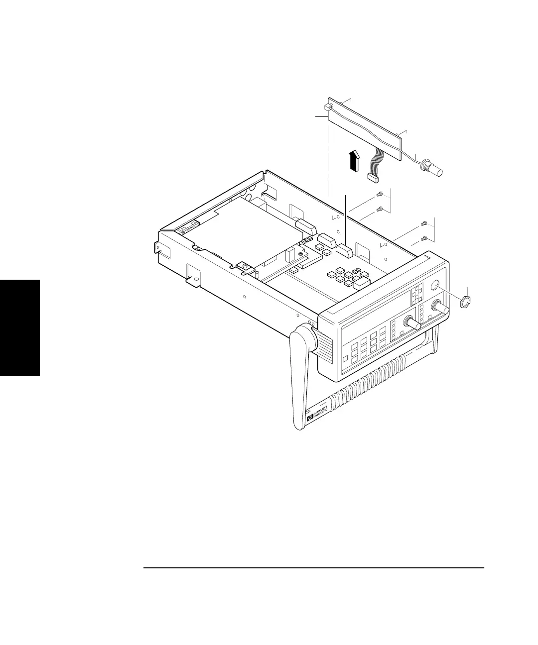
Figure 3-8. Optional Channel Input Assembly Removal
4 Disconnect flat-ribbon cable of the optional channel from
connector J7 of A1 Motherboard Assembly as shown in Figure 3-8.
5 Remove the four (two or three for Option 050 or 124) screws (H2)
attaching the optional channel to the chassis as shown in
Figure 3-8.
6 Remove the optional channel assembly.
H2
H2
W1
A3 3 GHz
Channel Assembly
(Shown with Option 015/030)
J7
H3