2
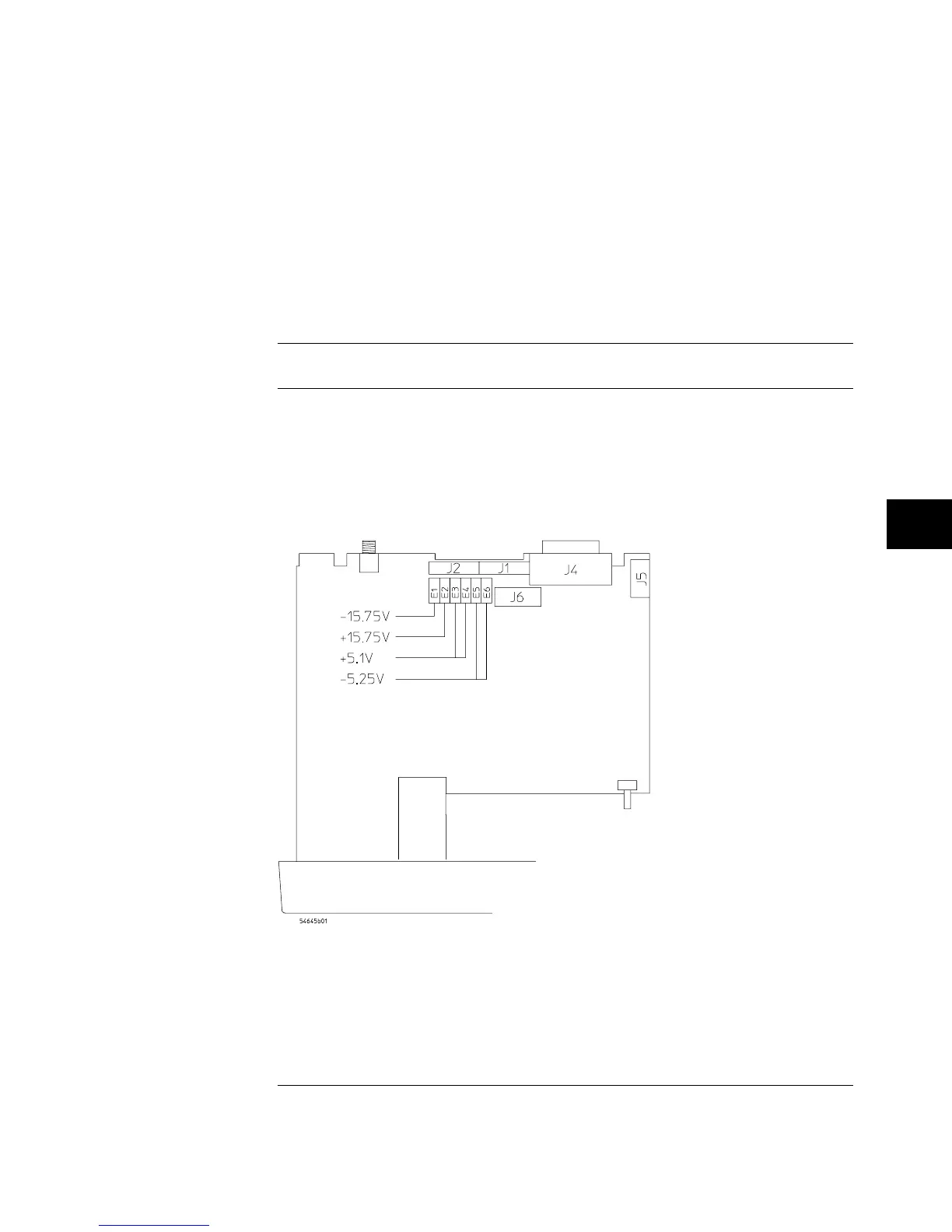
Measure the power supply voltages at E1 through E6 on the system
board.
The test points are not marked on the system board; see the following figure
for the location of test points.
Make sure that the voltage measurements are within the following tolerances.
Table 7-12
Power Supply Voltage Tolerances
Supply Voltage Tolerance
+
5.1 V
±
153 mV (
+
4.947 V to
+
5.253 V)
–5.25 V
±
158 mV (–5.092 V to –5.408 V)
+
15.75 V +1.260 V, –787 mV (
+
14.963 V to
+
17.010 V)
−
15.75 V
±
787 mV (
−
14.963 V to
−
16.537V)
Low Voltage Power Supply Voltage Test Points
(bottom side of oscilloscope)
Figure 7-4
Testing, Adjusting, and Troubleshooting
To adjust the power supply
7-31
 Loading...


