5
5500-24G-PoE+-4SFP HI (2 slots)/
5500-24G-PoE+-4SFP HI TAA (2 slots) panel views
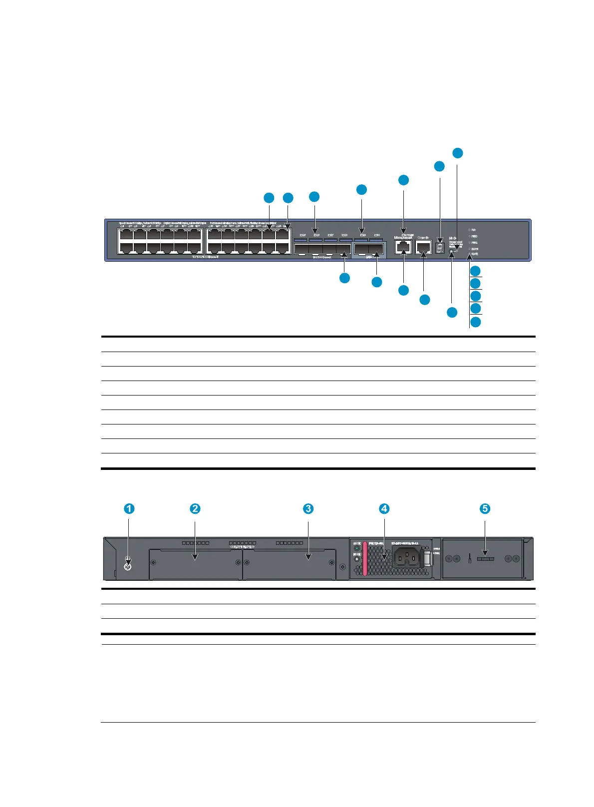
Figure 7 5500-24G-PoE+-4SFP HI (2 slots)/5500-24G-PoE+-4SFP HI TAA (2 slots) front panel
(1) 10/100/1000 Base-T auto-sensin
Ethernet port
(2) 10/100/1000 Base-T Ethernet port LED
(3) SFP port LED (4) SFP+ port LED
(5) Management Ethernet port LED (ACT/LINK) (6) Seven-segment LED (Unit)
(7) Port mode LED (Mode) (8) System status LED (SYS)
(9) Power supply 1 status LED (PWR1)
(10) Power supply 2 status LED (PWR2)
(11) Interface card 1 status LED (SLOT1) (12) Interface card 2 status LED (SLOT2)
(13) Port LED mode switchin
button
(14) Console port
(15) Mana
ement Ethernet port (Mana
ement)
(16) SFP+ port
(17) 100/1000 Base-X SFP port
Figure 8 5500-24G-PoE+-4SFP HI (2 slots)/5500-24G-PoE+-4SFP HI TAA (2 slots) rear panel
(1) Grounding screw (2) Interface card slot 1 (SLOT1)
(3) Interface card slot 2 (SLOT2) (4) Power supply slot 1 (PWR1)
(5) Power supply slot 2 (PWR2)
NOTE:
• The 5500-24G-PoE+-4SFP HI (2 slots) switch and 5500-24G-PoE+-4SFP HI TAA (2 slots) switch come
with two expansion interface card slots covered by filler panels.
• The 5500-24G-PoE+-4SFP HI (2 slots) switch and 5500-24G-PoE+-4SFP HI TAA (2 slots) switch come
with power supply slots empty.
1 2
3
4
5
6
7
8
9
10
11
12
13
14
15
16
17

 Loading...


