19
Grounding the switch with a grounding conductor buried in the
earth ground
If the installation site has no grounding strips, but earth ground is available, hammer a 0.5 m (1.64 ft) or
longer angle iron or steel tube into the earth ground to serve as a grounding conductor.
The dimensions of the angle iron must be at least 50 × 50 × 5 mm (1.97 × 1.97 × 0.20 in). The steel tube
must be zinc-coated and its wall thickness must be at least 3.5 mm (0.14 in).
Weld the yellow-green grounding cable to the angel iron or steel tube and treat the joint for corrosion
protection.
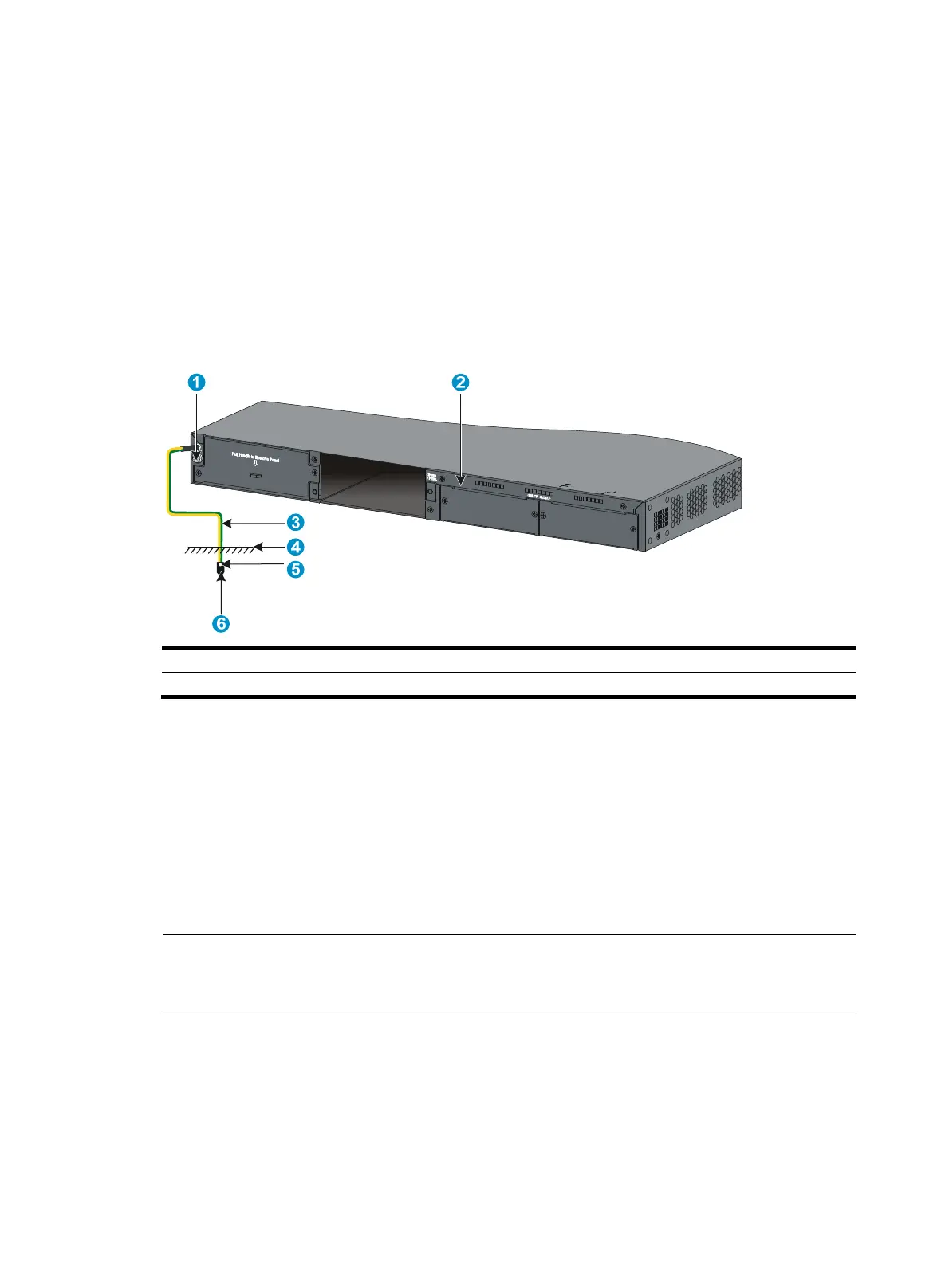
Figure 26 Grounding the switch by burying the grounding conductor into the earth ground
(1) Groundin
screw (2) Chassis
rear panel
(3) Groundin
cable
(4) Earth (5) Joint (6) Grounding conductor
Grounding the switch by using the AC power cord
If the installation site has no grounding strips or earth ground, you ground an AC-powered switch through
the PE wire of the power cord. Make sure that:
• The power cord has a PE terminal.
• The ground contact in the power outlet is securely connected to the ground in the power distribution
room or on the AC transformer side.
• The power cord is securely connected to the power outlet.
NOTE:
If the
round contact in the power outlet is not connected to the
round, report the problem and reconstruc
the grounding system.

 Loading...


