40
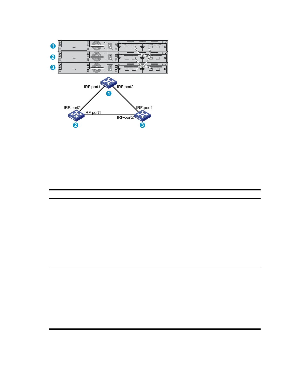
Figure 53 IRF fabric in ring topology
Identifying physical IRF ports on the member switches
Identify the physical IRF ports on the member switches according to your topology and connection
scheme.
Table 6 sho
ws the physical ports that can be used for IRF connection.
Table 6 Physical IRF port requirements
Switch model Candidate
h
sical IRF
orts
Re
uirements
5500-24G-4SFP HI (2
slots)
5500-24G-SFP HI (2
slots)
5500-24G-SFP HI TAA
(2 slots)
5500-24G-PoE+-4SFP
HI (2 slots)
5500-24G-PoE+-4SFP
HI TAA (2 slots)
• The two fixed SFP+ ports on
the front panel
• Ports on the 10GE XFP, SFP+,
CX4 interface cards on the
rear panel
The two SFP+ ports on the front panel and
10-Gigabit ports on the expansion interface
card can be bound to any IRF port.
5500-48G-4SFP HI (2
slots)
5500-48G-PoE+-4SFP
HI (2 slots)
5500-48G-PoE+-4SFP
HI TAA (2 slots)
• The two fixed SFP+ ports on
the front panel
• Ports on the 10GE XFP, SFP+,
CX4 interface cards on the
rear panel
• Physical ports on the same interface card
can only be bound to the same IRF port.
• SFP+ port numbered 53 on the front panel
can only be bound to the same IRF port as
physical ports on the interface card in slot
2.
• SFP+ port numbered 54 on the front panel
can only be bound to the same IRF port as
physical ports on the interface card in slot
1.

 Loading...


