11
Installing the switch in a 19-inch rack
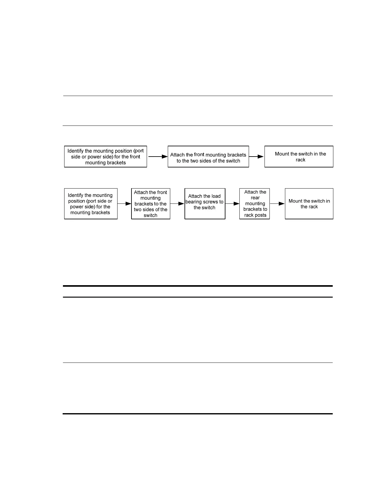
You can install a 5500 HI switch in a 19-inch rack by using one of the following methods:
• Use the front mounting brackets. Figure 12 sh
ows the mounting procedure diagram.
• Use the front and rear mounting brackets. Figure 13 sh
ows the mounting procedure diagram.
NOTE:
If a rack shelf is available, you can put the switch on the rack shelf, slide the switch to an appropriate
position, and attach the switch to the rack with mounting brackets.
Figure 12 Rack-mounting procedure (I)
Figure 13 Rack-mounting procedure (II)
Rack-mounting restrictions and guidelines
Follow the rack-mounting restrictions and guidelines in Table 4, depending on the mounting accessories
that you use.
Table 4 Rack-mounting restrictions and guidelines
Mountin
method
Restrictions and
uidelines
Rack-mounting by using front
mounting brackets
• Only applicable to the 5500-24G-4SFP HI (2 slots), 5500-48G-4SFP HI
(2 slots), 5500-24G-SFP HI (2 slots), and 5500-24G-SFP HI TAA (2 slots)
switches.
• Install the front mounting brackets at the port-side or power-side mounting
position as needed.
• For the 5500-48G-4SFP HI (2 slots), if you are installing an LSP5GP8P0
(JG314A) interface card, make sure the rack depth is 800 mm (31.50 in)
or 1000 mm (39.37 in).
Rack-mounting by using front
and rear mounting brackets
•
Only applicable to the 5500-24G-PoE+-4SFP HI (2 slots),
5500-24G-PoE+-4SFP HI TAA (2 slots), 5500-48G-PoE+-4SFP HI (2
slots), and 5500-48G-PoE+-4SFP HI TAA (2 slots) switches.
• Install the front mounting brackets at the port-side or power-side mounting
position as needed.
• Make sure the rack depth is 800 mm (31.50 in) or 1000 mm (39.37 in).
Mounting accessory kit

 Loading...


