43
Connecting the IRF member switches in a ToR solution
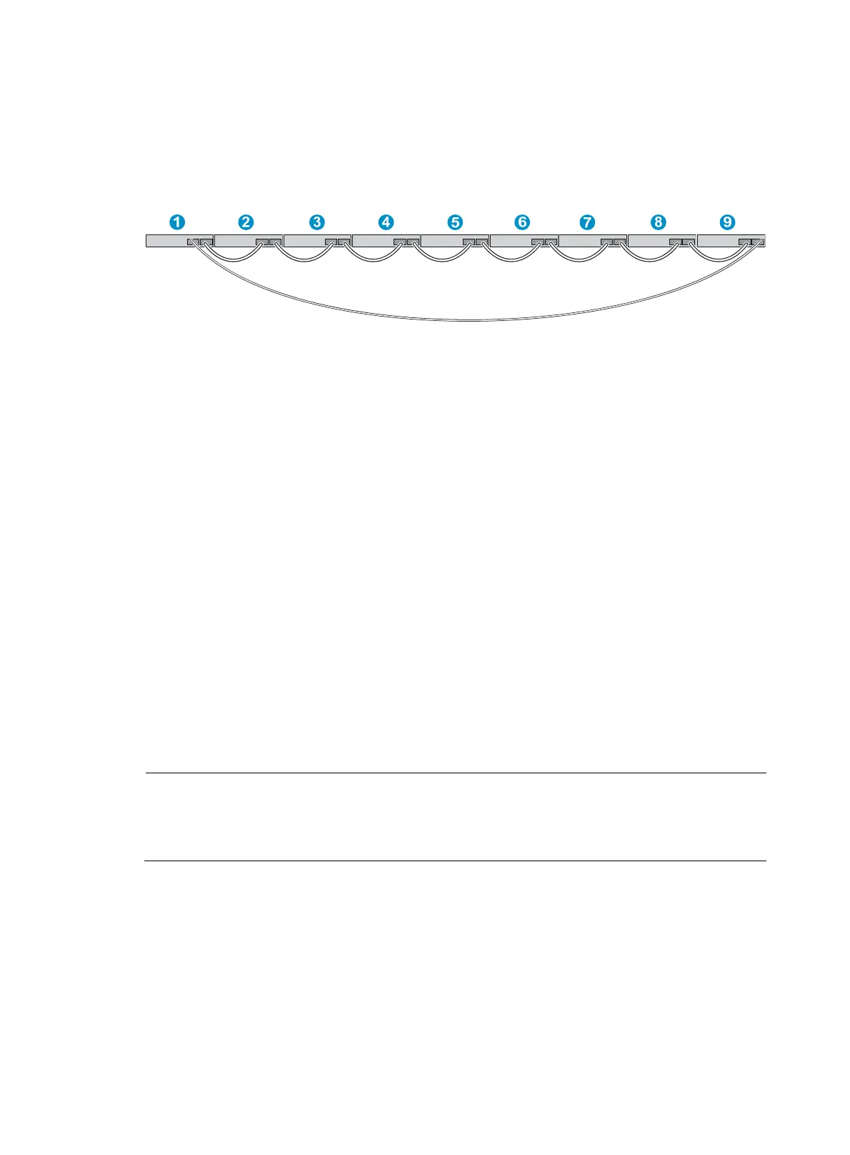
You can install IRF member switches in different racks side by side to deploy a top of rack (ToR)
solution. Figure 56 sho
ws an example for connecting nine top of rack IRF member switches by using SFP+
transceiver modules and optical fibers. The topology is the same as Figure 55.
Figure 56 Connecting top of rack switches
Configuring basic IRF settings
After you install the IRF member switches, power on the switches, and log in to each IRF member switch
(see HP 5500 HI Switch Series Fundamentals Configuration Guide) to configure their member IDs,
member priorities, and IRF port bindings.
Follow these guidelines when you configure the switches:
• Assign the master switch higher member priority than any other switch.
• Bind physical ports to IRF port 1 on one switch and to IRF port 2 on the other switch.
• To bind the ports on an interface card to an IRF port, you must install the interface card first. For how
to install an interface card, see "Installing/removing an inter
face card."
• Execute the display irf configuration command to verify the basic IRF settings.
For more information about configuring basic IRF settings, see HP 5500 HI Switch Series IRF
Configuration Guide.
Connecting the physical IRF ports
Use CX4/SFP+ cables or XFP/SFP+ transceiver modules and fibers to connect the IRF member switches
as planned.
NOTE:
ear an ESD-preventive wrist strap when you connect CX4/SFP+ cables or SFP+/XFP transceiver
modules and fibers. For how to connect them, see
SFP/SFP+/XFP Transceiver Modules Installation Guid
and "Installing/removing a CX4/SFP+ cable."
Accessing the IRF fabric to verify the configuration
To verify the basic functionality of the IRF fabric after you finish configuring basic IRF settings and
connecting IRF ports:
1. Log in to the IRF fabric through the console port of any member switch.
2. Create a Layer 3 interface, assign it an IP address, and make sure that the IRF fabric and the
remote network management station can reach each other.

 Loading...


