147
• On Switch C, create aggregation group 3 that corresponds to aggregation group 3 on the IRF virtual
switch.
Network requirements
You must upgrade the boot files of the IRF member switches and ensure packet forwarding for user network
using the following guidelines:
• The current boot file on each IRF member switch is soft-version1.bin. The new boot file soft-version2.bin
is saved on the TFTP server. You must perform remote ISSU for the IRF virtual switch.
• The IP address of the IRF virtual switch is 1.1.1.1/24, and that of the TFTP server is 2.2.2.2/24. The IRF
virtual switch and the TFTP server can reach each other.
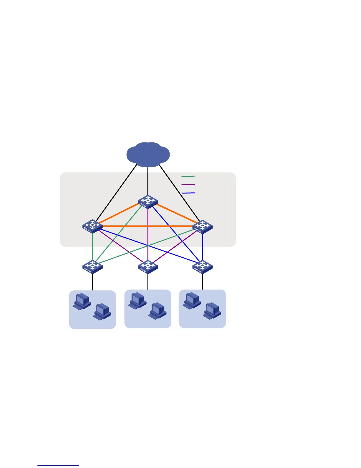
Network diagram
Figure 2 Network diagram
IRF virtual
device
Switch A Switch B Switch C
Switch D
Switch E
1
23
4
5
6
7
8
1: GE1/0/1
2: GE1/0/2
3: GE1/0/3
9
7: GE3/0/1
8: GE3/0/2
9: GE3/0/3
Switch F
4: GE2/0/1
5: GE2/0/2
6: GE2/0/3
1
2
3
1
2
3
1
2
3
1: GE1/0/1
2: GE1/0/2
3: GE1/0/3
1: GE1/0/1
2: GE1/0/2
3: GE1/0/3
1: GE1/0/1
2: GE1/0/2
3: GE1/0/3
Users
Users Users
Core
Aggregation group 1
Aggregation group 2
Aggregation group 3
 Loading...


