6-17Removal and Replacement
PRIMER ASSEMBLY AND SENSOR REMOVAL
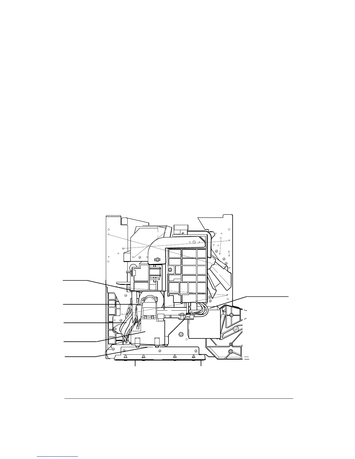
To remove the primer assembly and sensor, perform the following steps:
1. Remove the window assembly.
2. Remove the left endcover.
3. Disconnect the primer assembly and sensor cable connector.
4. Disconnect the four rubber tubes from the primer assembly.
5. Using a TORX T-20 and extension bit, remove the two bottom screws and loosen the
top screw, that attach the primer assembly to the left sideplate. See Figure 6-11.
6. Slide the primer assembly out from the plotter.
7. To remove the optical sensor from the primer assembly, use a TORX T-10 screwdriv-
er and remove the two screws that attach the sensor to the primer assembly.
Figure 6-11.
Screws (2)
Screw
Primer
(C)C2858-76
Assembly
Tubes (4)
Optical Sensor
Cable
Connectors