5-24. ALC GAIN ADJUSTMENT (UPDATES) (Cont'd)
1740A
OSCILLOSCOPE
MODE
......................................................
MAIN
CHANNELAINPUT
............................................
AC
.............................................
CHANNEL A V/DIV
%V
............................................
CHANNEL
B
INPUT
DC
..............................................
CHANNELBV/DIV 1V
........................................................
DISPLAY A
3.
Adjust 1740A vertical and horizontal position knobs for waveform at the center of
oscilloscope CRT. Adjust START knob, below SWP button, for 10 kHz as displayed on
oscilloscope. Turn MODULATION RANGE
Hz
to 100 and VERNIER to
10K.
4. Connect equipment as shown in Figure 5-25.
5. On
1740A select A vs
B
MODE
and set CHANNEL A to .OO5/DIV.
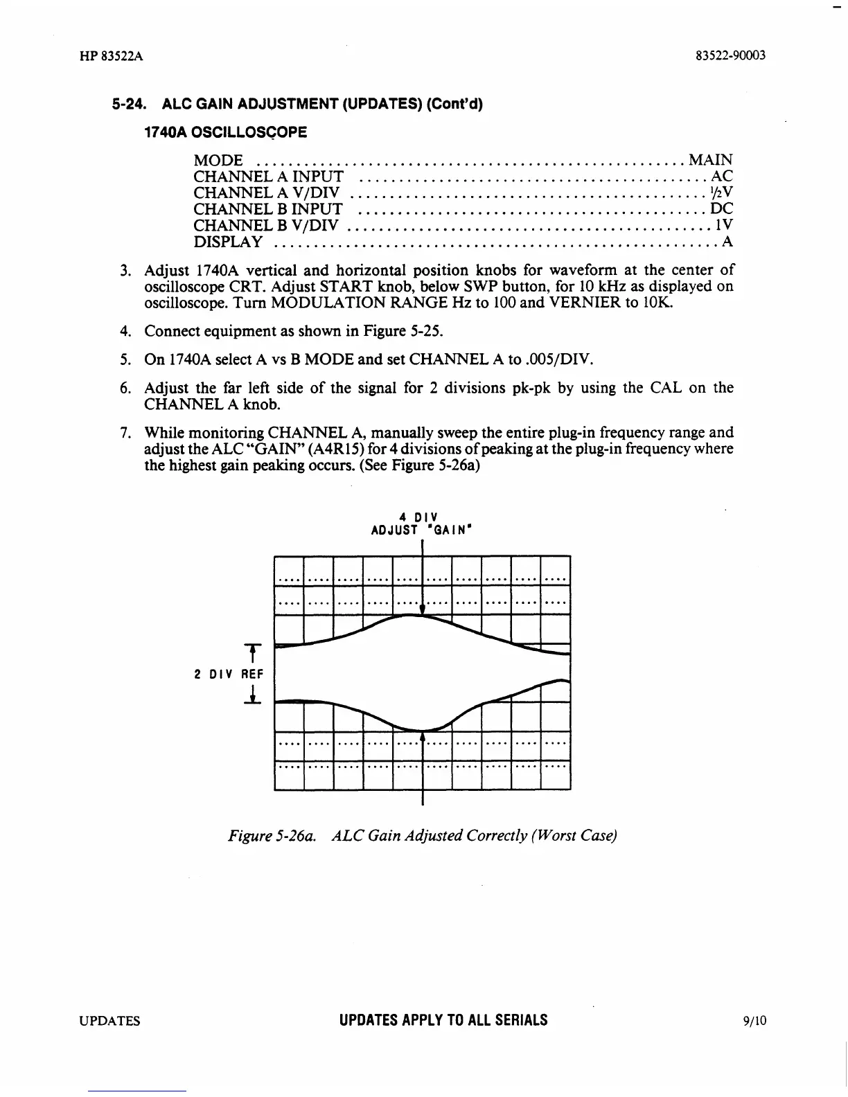
6.
Adjust the far left side of the signal for
2
divisions pk-pk by using the
CAL
on the
CHANNEL A knob.
7. While monitoring CHANNEL A, manually sweep the entire plug-in frequency range and
adjust the ALC "GAIN
(A4R15) for 4 divisions of peaking at the plug-in frequency where
the highest gain peaking occurs. (See Figure
5-26a)
4
DIV
ADJUST
'GAIN'
f
2
DIV
REF
I
Figure
5-26a.
ALC
Gain
Adjusted
Correctly (Worst Case)
UPDATES
UPDATES APPLY TO ALL SERIALS