5-27.
MARKER AND SAMPLER ADJUSTMENTS (UPDATES)
NOTE
This procedure assumes that
A3S1
is
set to the factory-set position
(Table
5-6).
REFERENCE
Performance Test: Paragraph
4-1
6
Service Sheets:
A7
and
A8
DESCRIPTION
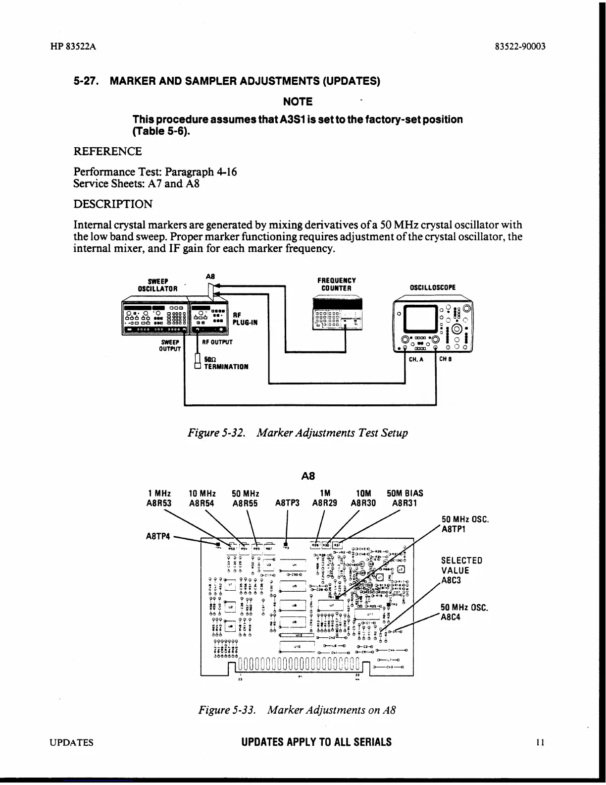
Internal crystal markers are generated by mixing derivatives of a
50
MHz
crystal oscillator with
the low band sweep. Proper marker functioning requires adjustment of the crystal oscillator, the
internal mixer, and IF gain for each marker frequency.
OSCILLATOR
RF
OUTWT
TERMINAT ION
FREQUENCY
COUNTER
OSCILLOSCOPE
Figure
5-32.
Marker Adjustments Test
Setup
1 MHz 10 MHz 50MHz 1M 10M 50MBIAS
A8R53 A8R54 A8R55 A8TP3 A8R29 A8R3O A8R31
Figure
5-33.
Marker Adjustments on
A8
UPDATES
UPDATES APPLY
TO
ALL SERIALS