5-27.
MARKER AND SAMPLER ADJUSTMENTS (UPDATES) (Cont'd)
EQUIPMENT:
FREQUENCY COUNTER
...................................
HP 536A
OSCILLOSCOPE
......................
,
....................
HP 436A
PROCEDURE:
NOTE
Turn
ac power off when removing or installing
PC
boards.
1.
Place A8 assembly on extender board. Connect equipment as shown in Figure 5-32. For all
adjustments and test point locations refer to Figure 5-33 Marker Adjustments on
A8
or
Figure 5-36 Marker Adjustments on A7. Terminate
83522A RF output in 50 Ohms. Set
1740A oscilloscope to A vs B sweep mode to obtain horizontal deflection as a function of
the
8350A/B SWEEP OUT.
2. Set
8350A/B STARTISTOP sweep for 10 MHz to 2.0 GHz. Select 83522A AMPTD
MARKERS. Connect counter with
1:l capacitive probe to A8TPl. Adjust A8C4 start for
frequency counter indication of 50 MHz
+250Hz. If A8C4 does not have the range
required to adjust the 50 MHz crystal oscillator, select a new
value for A8C3. (An increase
in capacitance will decrease frequency).
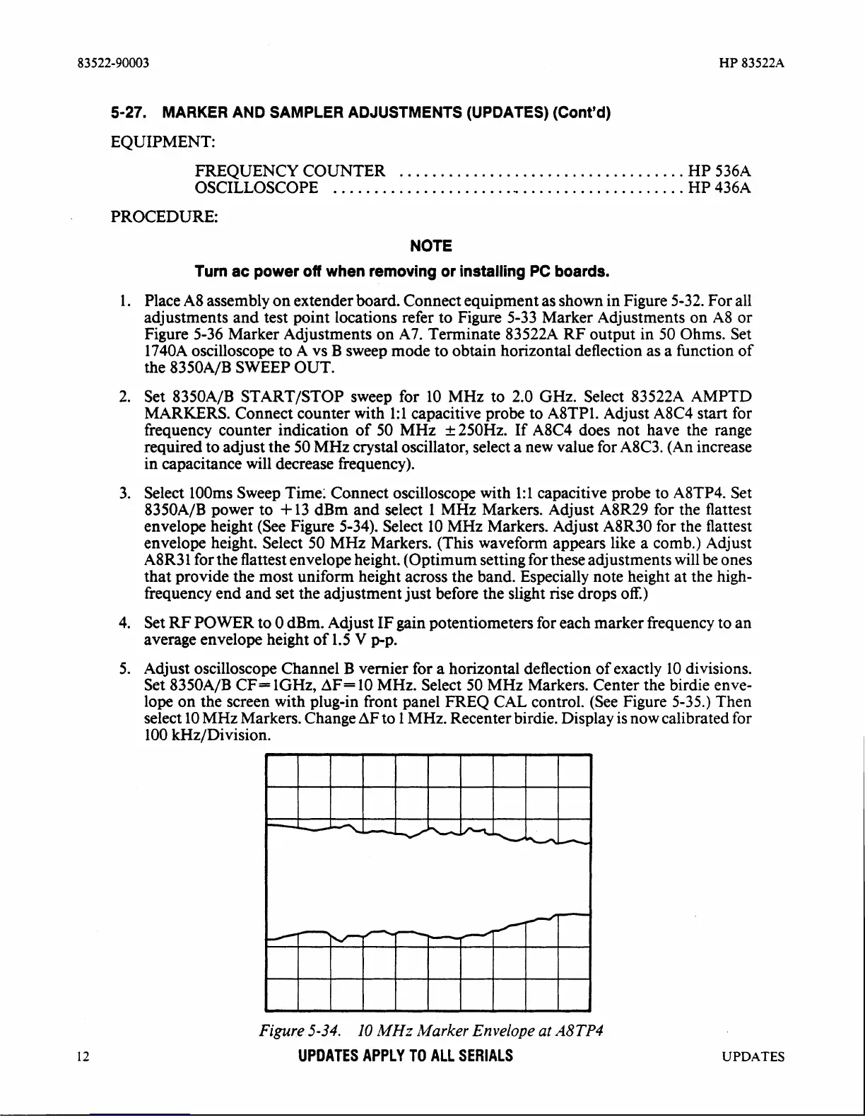
3. Select
looms Sweep Time: Connect oscilloscope with 1:l capacitive probe to A8TP4. Set
8350A/B power to
+
13 dBm and select 1 MHz Markers. Adjust A8R29 for the flattest
envelope height (See Figure 5-34). Select 10 MHz Markers. Adjust
A8R30 for the flattest
envelope height. Select 50 MHz Markers. (This waveform appears like a comb.) Adjust
A8R31 for the flattest envelope height. (Optimum setting for these adjustments will be ones
that provide the most uniform height across the band. Especially note height at the high-
frequency end and set the adjustment just before the slight rise drops
oE)
4. Set
W
POWER to 0 dBm. Adjust IF gain potentiometers for each marker frequency to an
average envelope height of 1.5
V
pp.
5. Adjust oscilloscope Channel B vernier for a horizontal deflection of exactly 10 divisions.
Set
8350A/B CF- lGHz,
AF=
10 MHz. Select 50 MHz Markers. Center the birdie enve-
lope on the screen with plug-in front panel FREQ CAL control. (See Figure 5-35.) Then
select 10 MHz Markers. Change
AF
to 1 MHz. Recenter birdie. Display is now calibrated for
100
kHz/Division.
Figure5-34.
10
MHz MarkerEnvelopeatA8TP4
UPDATES APPLY TO
ALL SERIALS
UPDATES