5-27A. MARKER GAIN ADJUSTMENT (Fine Tune) (UPDATES) (Cont'd)
3312A FUNCTION GENERATOR
SINEWAVE
....................................................
ON
AMPLITUDE
...............................................
10
V
P-P
FREQUENCY
.................................................
5Hz
8755C SWEPT AMPLITUDE ANALYZER
DB/DIV
.......................................................
5dB
REFERENCE LEVEL
..........................................
-
2
dB
VERNIER
.....................................................
OW
PROCEDURE:
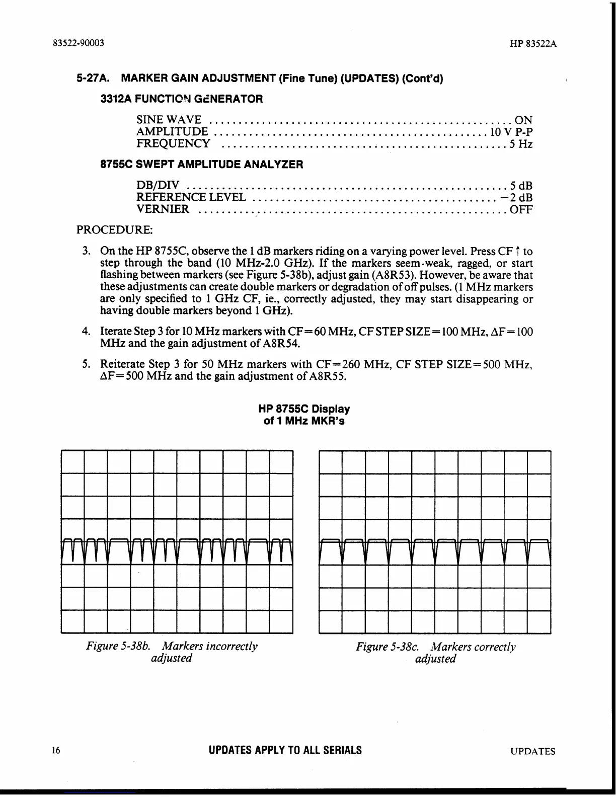
3. On the HP
8755C, observe the 1 dB markers riding on a varying power level. Press
CF
f
to
step through the band (10 MHz-2.0
GHz). If the markers seem-weak, ragged, or start
flashing between markers (see Figure
5-38b), adjust gain (A8R53). However, be aware that
these adjustments can create double markers or degradation of off pulses. (1 MHz markers
are only specified to 1
GHz CF, ie., correctly adjusted, they may start disappearing or
having double markers beyond 1
GHz).
4. Iterate Step 3 for 10 MHz markers with CF= 60 MHz, CF STEP SIZE= 100 MHz, AF= 100
MHz and the gain adjustment of
ABR54.
5.
Reiterate Step
3
for 50 MHz markers with CF=260 MHz, CF STEP SIZE= 500 MHz,
AF= 500 MHz and the gain adjustment of
A8R55.
HP
8755C Display
of
1
MHz
MKR's
Figure 5-38b. Markers incorrectly
adiusted
Figure 5-38c. Markers correctly
adjusted
UPDATES APPLY
TO
ALL SERIALS
UPDATES