5-28.
EXTERNAL MARKER ADJUSTMENT (UPDATES)
REFERENCE:
Service Sheet: A8.
DESCRIPTION:
A
rear panel BNC jack is available for external marker sources. A8R67 provides gain adjustment
to the video amplifier for marker presence.
When using the HP
8755C with external markers, factory select resistor A8R28 reduces the
feedthrough, but degrades internal markers.
EQUIPMENT:
RF
Marker Source
.................................
HP
8350A/B/83522A
Swept Amplitude Analyzer
...................................
HP 8755C
Detector
.................................................
HP
11
664B
Oscilloscope
...............................................
HP
1740A
10
dB
Attenuator
.................................
HP 8491A Option 010
RF MARKER SOURCE
SWEEP
OSCILLAT
0
R
R
F
PLUG-IN
OUTPUT OUTPUT
10
dB
AITENUATOR
4"
SWEPT AMPLITUDE
ANALYZER
DETECTOR
I
-
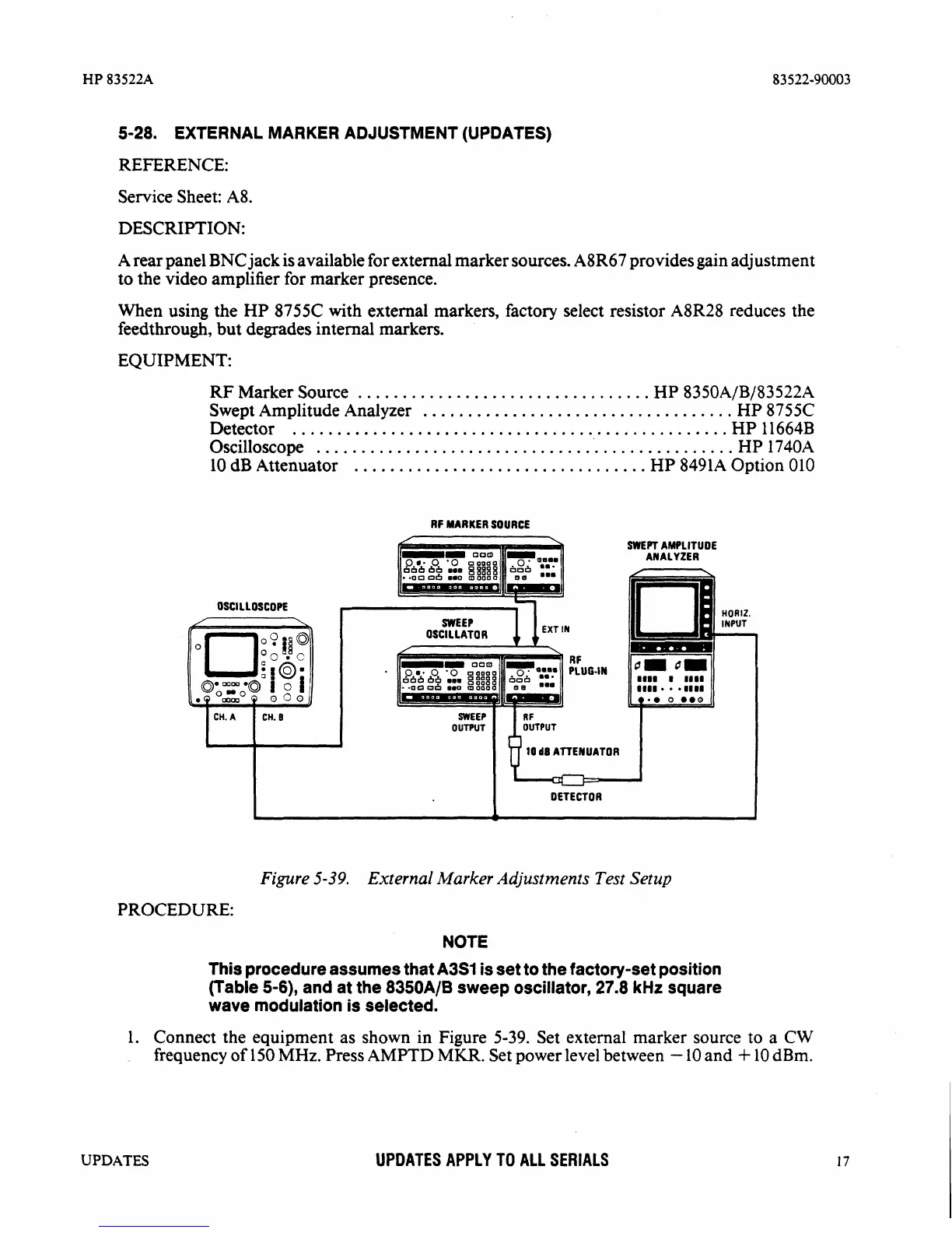
Figure
5-39.
External
Marker
Adjustments
Test
Setup
PROCEDURE:
NOTE
This
procedure assumes that
A3S1
is set to the factory-set position
(Table
5-6),
and at the 8350AlB sweep oscillator, 27.8
kHz
square
wave
modulation is selected.
1.
Connect the equipment as shown in Figure 5-39. Set external marker source to
a
CW
frequency of 150
MHz.
Press
AMPTD
MKR.
Set power level between
-
10 and
+
10 dBm.
UPDATES
UPDATES APPLY TO ALL SERIALS