5-28.
EXTERNAL MARKER ADJUSTMENT (UPDATES)
(Cont'd)
2. Set RF plug-in to
be
adjusted in EXT and AMPTD
MKR
MODES. On the 8350AIB select a
START frequency
=
50 MHz, STOP frequency
=
250 MHz, and a sweep speed
=
17 ms.
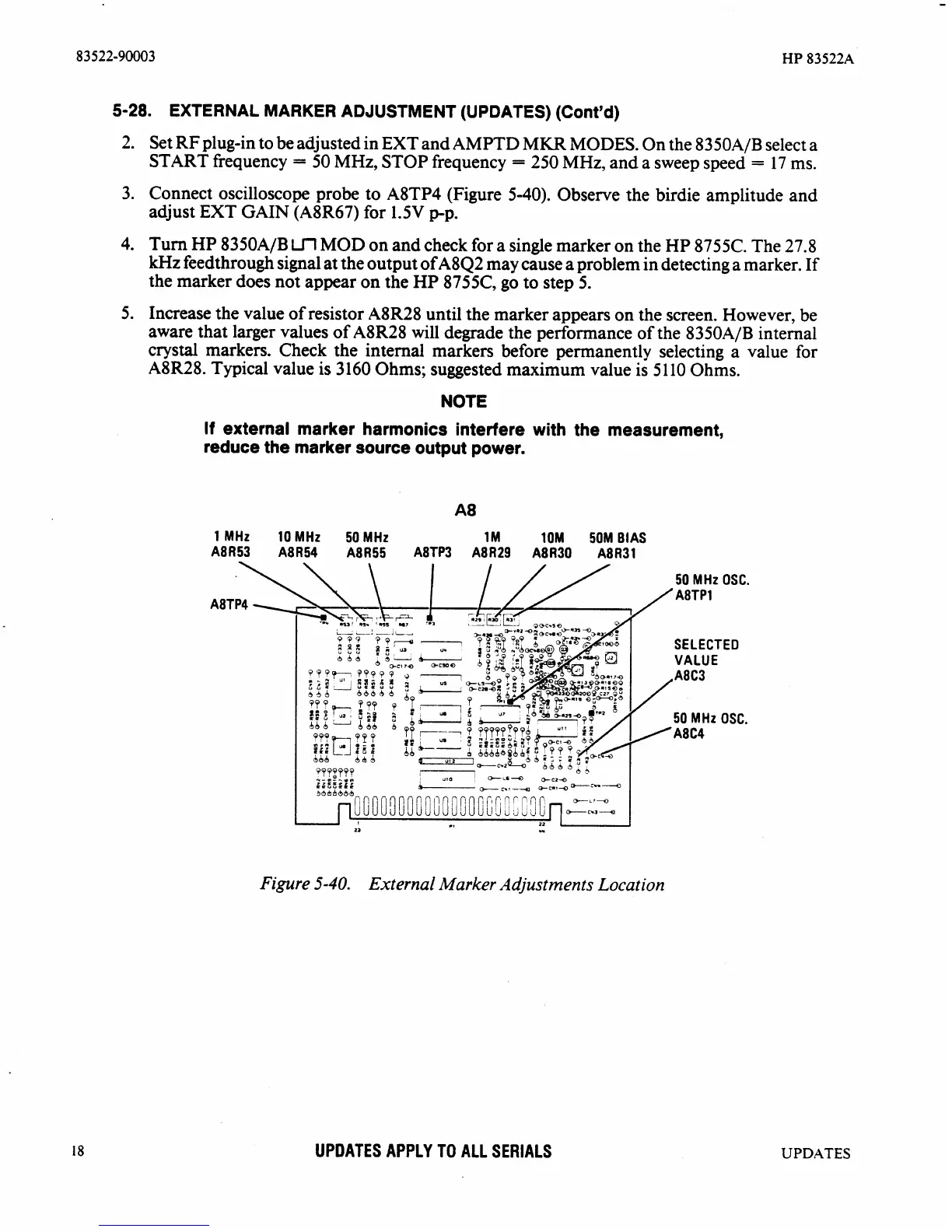
3. Connect oscilloscope probe to
A8TP4 (Figure 5-40). Observe the birdie amplitude and
adjust EXT GAIN
(A8R67) for
1.5V
gp.
4. Turn HP 8350A/B
Ul
MOD on and check for
a
single marker on the HP 8755C. The 27.8
kHz
feedthrough signal at the output of A8Q2 may cause a problem in detecting a marker. If
the marker does not appear on the HP
8755C, go to step 5.
5. Increase the value of resistor
A8R28 until the marker appears on the screen. However, be
aware that larger values of
A8R28 will degrade the performance of the 8350AIB internal
crystal markers. Check the internal markers before permanently selecting a value for
A8R28. Typical value is 3160 Ohms; suggested maximum value is
5
110
Ohms.
NOTE
If
external marker harmonics interfere with the measurement,
reduce the marker source output power.
1 MHz 10 MHz 50MHz 1M
1OM
50M BIAS
A8R53 A8R54 A8R55 A8TP3 A8R29 A8R30 A8R31
50 MHz OSC.
A8TP1
SELECTED
VALUE
A8C3
50 MHz OSC.
A8C4
8
-8,
"I-m-7.V"
LLGZLL6
34bh464
-
c*,-
Q-en14
-c*--
~0000~00C01;~~~OCi;[i3~C3[i~_O-~~Z
1
23
.,
22
w
Figure
5-40.
External
Marker
Adjustments Locat ion
UPDATES APPLY
TO
ALL SERIALS
UPDATES