A4 ALC TROUBLESHOOTING (CHANGE
8)
(Cont'd)
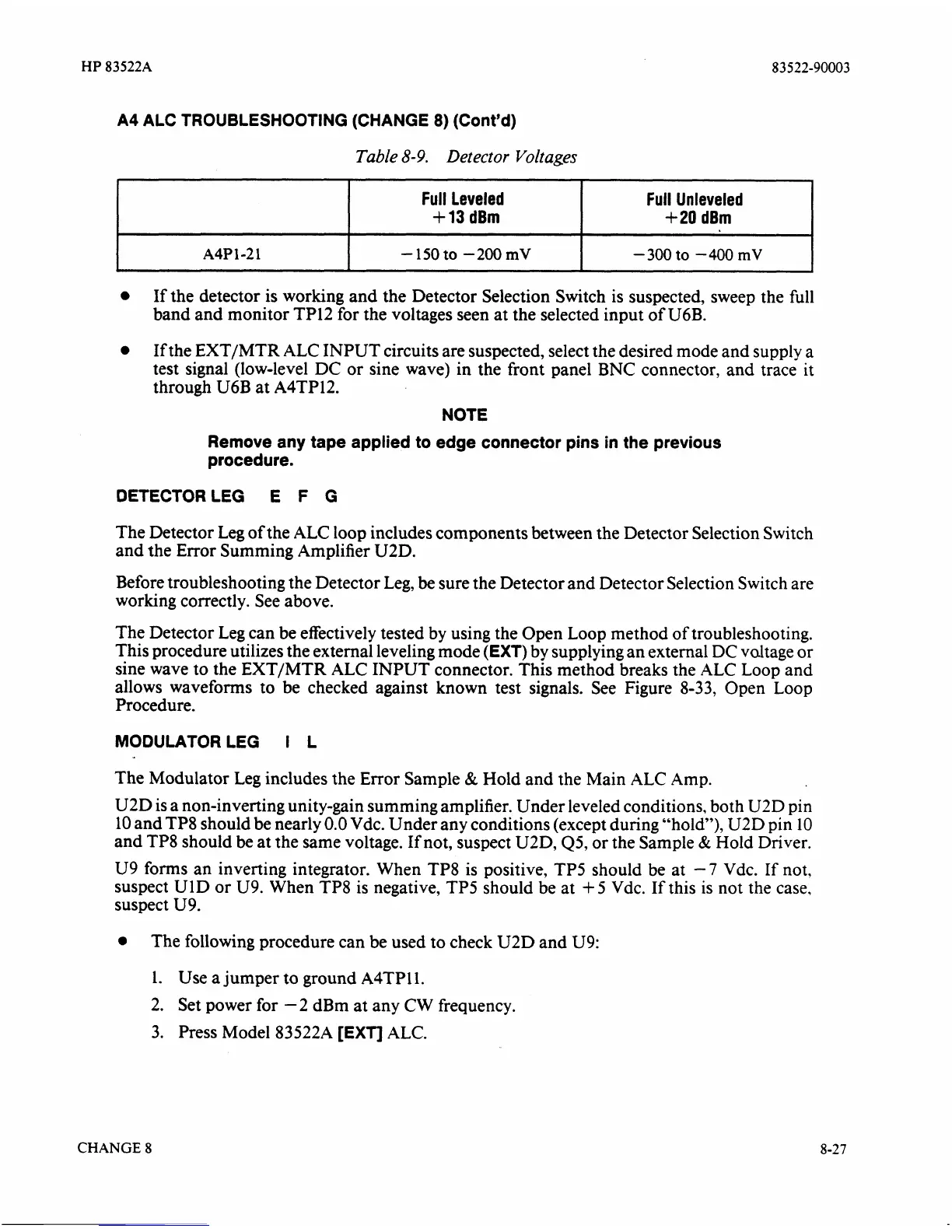
Table
8-9.
Detector Voltages
If the detector is working and the Detector Selection Switch is suspected, sweep the full
band and monitor TP12 for the voltages seen at the selected input of
U6B.
A4P
1-2 1
i
If the EXTIMTR
ALC
INPUT circuits are suspected, select the desired mode and supply a
test signal (low-level DC or sine wave) in the front panel BNC connector,
and
trace it
through U6B at
A4TP12.
NOTE
Full Leveled
+
13
dBm
-150
to
-200
mV
Remove any tape applied to edge connector pins in the previous
procedure.
Full Unleveled
+20
dBm
-300
to
-400
mV
DETECTORLEG E
F
G
The Detector Leg of the
ALC
loop includes components between the Detector Selection Switch
and the Error Summing Amplifier
U2D.
Before troubleshooting the Detector Leg,
be
sure the Detector and Detector Selection Switch are
working correctly. See above.
The Detector Leg can be effectively tested by using the Open Loop method of troubleshooting.
This procedure utilizes the external leveling mode
(EXT)
by supplying an external
DC
valtage or
sine wave to the
EXT/MTR
ALC
INPUT connector. This method breaks the
ALC
Loop and
allows waveforms to be checked against known test signals. See Figure 8-33, Open Loop
Procedure.
MODULATOR LEG
I
L
The Modulator Leg includes the Error Sample
&
Hold and the Main ALC Amp.
U2D is a non-inverting unity-gain summing amplifier. Under leveled conditions, both
UZD
pin
10 and TP8 should be nearly
0.0
Vdc. Under any conditions (except during "hold"), U2D pin 10
and TP8 should be at the same voltage. If not, suspect
U2D, Q5, or the Sample
&
Hold Driver.
U9
forms an inverting integrator. When TP8 is positive, TP5 should be at
-7
Vdc. If not,
suspect
U1D or U9. When TP8 is negative, TP5 should be at
+
5 Vdc. If this is not the case,
suspect U9.
The following procedure can be used to check U2D and
U9:
1.
Use
a
jumper to ground A4TPll.
2.
Set power for -2 dBm at any CW frequency.
3. Press Model
83522A
[EXT]
ALC.
CHANGE
8