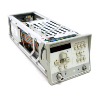
Service Model
83522A
RF Section
The RF Section includes the high-frequency microcircuits and their bias
components which produce, amplify, and control the amplitude of the RF
output.
The 0.01 to
2.4
GHz frequency range is covered with a YIG Oscillator (YO) as
the tunable source. A fixed 3.8
GHz oscillator is used to mix down the YO
output, thus covering the 0.01 to
2.4
GHz range.
A
directional coupler with a detector senses the RF power level and sends a
voltage to the ALC circuits for internal power leveling. Another coupler samples
the output for use in the Marker Generation circuits.
In Option 002 instruments, a programmable step attentuator is included to
provide up to -70 dB of additional output power control range.
DETAILED BLOCK DIAGRAM DESCRIPTION
DIGITAL CONTROVFRONT PANEL
A3 Digital Interface
The A3 Digital Interface Assembly acts as the 83522's distribution center,
receiving digital commands from the
8350A Sweep Oscillator and routing them
to the appropriate assembly within the plug-in.
The Buffer receives the digital control (including timing), data, and address
signals from the
8350A Sweep Oscillator's Instrument Bus. The control and
address lines are uni-directional and pass only to the plug-in, whereas the data
lines are bi-directional and carry information both to and from the plug-in. A
single buffer returns the plug-in flag (L PIFLG) to the
83504 indicating that a
plug-in front-panel key was pushed.
The Address Decoder provides the major control lines which eventually direct
data to the correct part of the plug-in. Address and control lines are decoded to
produce "enable lines": two for ROM; three for the Configuration Switches1
Interrupt Control;
five for the Front Panel; and two for the remainder of the
plug-in assemblies.
The ROM (Read Only Memory) stores program software and constants used by
the
8350A microprocessor while executing routines dedicated to the plug-in.
Two address decoding lines plus twelve address lines select the byte of data to be
sent back to the
8350A.
The Configuration SwitchIInterrupt Control circuits serve a dual purpose. The
Configuration Switch encodes information about the plug-in (including
frequency range, power, etc.), options used, and certain user-defined parameters.
During
INSTR
PRESET
and power-on, the switch positions are read by the
8350A microprocessor, then used to display the correct frequencies, markers,
power, and other parameters which vary from plug-in to plug-in. As Interrupt
Control, the circuits monitor the L SIRQ line, and send an interrupt
(L
PIIRQ)
to the
8350A to begin the bandswitch in multi-band plug-ins. During
bandswitch, the Interrupt Control is programmed to count down time intervals
specified by the microprocessor. At the end of these intervals, the
L
PIIRQ line
is again activated to notify the
8350A that the time interval has elapsed.

 Loading...