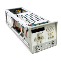
Model
83522A
Service
The RF Plug-in Interface buffers the data and address lines for use throughout
the rest of the RF plug-in. The data bus is bi-directional, so that the
8350A can
read information from the
A2
Front Panel Interface and A6 YO Driver
assemblies. The control lines, which complete the internal bus, come directly
from the Address Decoder. This internal bus sends controls messages and data
for
DACs to Digital Interface circuits on each assembly. These digital interface
circuits are essentially buffers between the digital and analog circuits.
A2
Front Panel Interface
A1
Front Panel
NOTE
Due to their strong functional interrelation, the
A2
Front
Panel Interface and
A1
Front Panel assemblies are discussed
together.
The
A2
Front Panel Interface and A1 Front Panel assemblies are primarily
responsible for displaying the status and power level of the RF plug-in, and
transmitting pushbutton and RPG commands back to the
8350A Sweep
Oscillator for processing. Front panel analog adjustments, and the analog
lV/GHz rear-panel output, are also processed on these assemblies.
The
Keyboard/Display Interface performs two functions. As a Keyboard
Interface, it strobes the columns of the Pushbutton Switch Matrix, while sensing
the row lines. When a key is pushed, the row line tracks the
strobed column line
corresponding to that key. The Keyboard Interface detects this, sets the FLAG
line to alert the
microprocess~r, and transmits the encoded key information
back to the
8350A for processing. As a Display Interface, the same column
strobes are buffered and used to drive the digits of the Power Display. While a
digit is enabled, the appropriate seven-segment data, stored inside the Display
Interface, is buffered to drive the segments. The scanning is done at a fast rate to
avoid flickering.
The Annunciator Interface stores data to drive the LED Annunciators which
display the status of various functions. Two special annunciators
-
MARKER
and UNLEVELED
-
are not digitally controlled, but are driven from separate
MkrIUnlvl circuits which monitor the Marker and ALC assemblies.
The Power Control Interface digitally controls several functional areas. Three of
the lines are buffered by the Attenuator Control, which operators the A19 Step
Attenuator in instruments equipped with Opt 002. The RF On circuits control
the biasing for the A12
YIG Oscillator and A14 Amplifier. When the RF is
turned off, the bias to these assemblies is removed, shutting off the oscillator
and amplifier.
The Frequency Tracking Amplifier and
lV/GHz blocks are the only active
analog circuits on the
A2
and A1 assemblies. The Frequency Tracking
Amplifier monitors the YO DRIVE V, a voltage proportional to the
YO'S
frequency. Its output tracks the
RF
output frequency, and is used to compensate
for frequency-dependent nonlinearities in the ALC loop. The
lV/GHz circuit
further processes this signal to produce a rear panel output supplying
lVdc per
GHz of output frequency for use with external equipment.

 Loading...