V
TUNE
(SWEEP
OUT)
A4
SWEEP
h
IA
l8
OSCILLATOR
FUNCTION
GENERATOR
000
o?
000
DOOOO
bz:
PLUG-IN
.
.om
GC3
000
00000
~n~~~oo~o~~~o~~~~.?
-
I
EXTiMTR
ALC
INPUT
TPl
I
5OmVIDIV
ImsIDIV
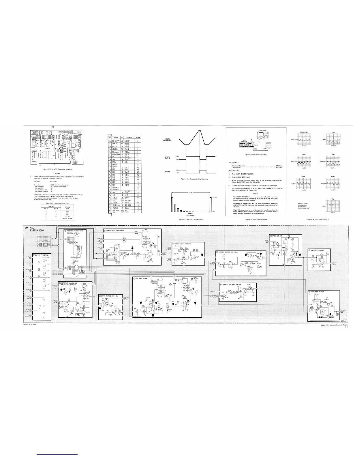
Open Loop Procedure Test Setup
L
RFB
A4P1-29
DCRI
Of)
1
22
,
DCRB-E)
23
PI
91)
EQUIPMENT:
Function Generator.
.......................................
HP 33 12A
Oscilloscope.
..............................................
HP 1740A
Figure
8-30.
A4 ALC, Component Locations
PROCEDURE:
I
NOTES
1. Press 8350A INSTR PRESET
.
I
1.
THE FOLLOWING KEY ENTRIES PROVIDE FRONT PANEL ACCESS FOR A DATA WRITE/READ
OPERATION TOIFROM THE ADDRESSED LOCATION:
2. Press 83525A
ALC.
I
Figure
8-31.
Retrace Blanking Waveform
3. Adjust Function Generator output for a 50 mV p-p sine wave at 500 Hz.
Adjust the OFFSET knob for -25
mVdc.
FUNCTION
KEY
ENTRY
"Hex Address Entry
(enter hex address)
Hex Data WRITE
two hex digits)
Hex Data READ
Hex Data Rotation Write
Hex Addressed Fast Read
4.
Connect Function Generator output to
EXTIMTR ALC connector.
5.
Set oscilloscope DISPLAY to A and TRIGGER COMP to
B.
Check for
the waveforms shown in Figure 8-34.
NOTE
I
"TO ADDRESS A DIFFERENT LOCATION, PRESS MI
AND ENTER THE NEW ADDRESS, OR
USE THE INCREMENT KEYS
TO
STEPTO THE NEW ADDRESS.
TO PREVENT THE MICRO OR FROM SERVICING THE RETRACE
INTERRUPT, PRESS
8350A CW
.
The HP 3312 OFFSET knob may have to be adjusted slightly to produce
the waveforms given in Figure 8-34. If the
EXT/MTR ALC input goes
positive, the Log Amp will saturate.
Table
8-1 0.
Leveling Control Lines
I
I
i
Adjustment of the EXT/MTR ALC CAL knob will affect the waveforms
at TP4, TW, and TP6. Adjust the CAL knob until these waveforms are
obtained.
"POWER
=
13
dBm
Offset depends on
Power Level and
EXTIMTR ALC "CAL."
Data
Bus Leveling
Mux
A1
Mux
A0
Ill
Mode
Slight differences may be noted between the waveforms shown in
Figure 8-34 and those obtained on individual ALC assemblies. This is
due to the many adjustments on the A4 assembly.
I
H
I
H
I
INTO
I
I
H
I
L
I
INT
1
I
L
H
EXT DET
L
L
POWER
METER
Press:
S
H
l
FT
50
Figure
8-32.
ALC DAC Test Waveform
Figure
8-33.
Open Loop Procedure
Figure
8-34.
Open Loop Waveforms
SERIAL
PREFIX:
2040A
Figure
8-35.
A4
ALC, Schematic Diagram