Adjustments
ADJUSTMENTS
Model
83522A
5-1
7.
FREQUENCY ACCURACY (Cont'd)
FREQUENCY
COUNTER
SWEEP
R F
OSCILLATOR PLUG-IN
A,,,-,
RF
OUTPUT
I
10
dB
ATTENUATOR
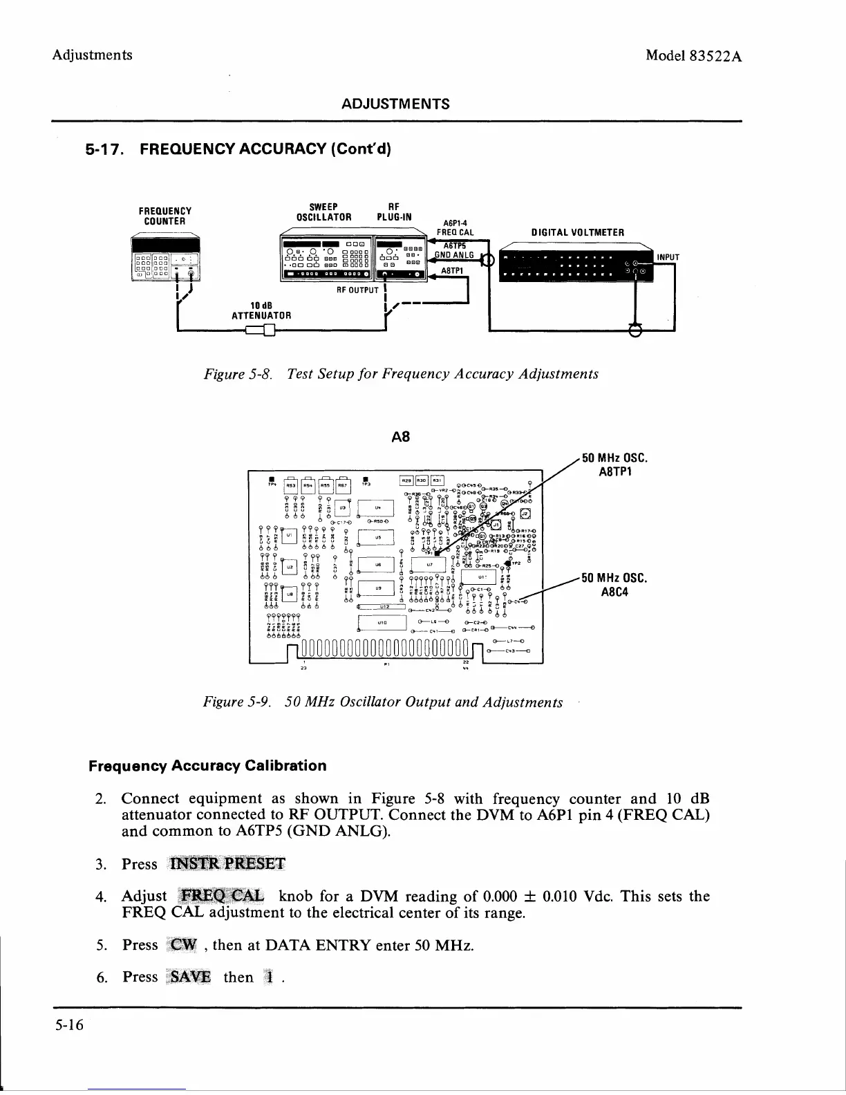
Figure 5-8.
Test Setup for Frequency Accuracy Adjustments
A8
/
50
MHz
OSC.
50
MHz
OSC.
A8C4
Figure 5-9.
50
MHz
Oscillator Output and Adjustments
Frequency Accuracy Calibration
2.
Connect equipment as shown in Figure 5-8 with frequency counter and 10 dB
attenuator connected to
RF
OUTPUT. Connect the DVM to A6P1 pin
4
(FREQ CAL)
and common to A6TP5 (GND ANLG).
3.
Press
IRSTR
PIKESET
4.
Adjust
CAL
knob for
a
DVM reading of 0.000
f
0.010
Vdc. This sets the
FREQ CAL adjustment to the electrical center of its range.
5.
Press
CW
,
then at DATA ENTRY enter 50 MHz.
6. Press
8kW
then