Adjustments
ADJUSTMENTS
Model 83522A
5-1
7.
FREQUENCY ACCURACY (Cont'd)
HEXADECIMAL
I
DEClMAL
0
thru
9
=
0
thru
9
A
=
10
b
=
11
C
=
12
d
=
13
E
=
14
F
=
15
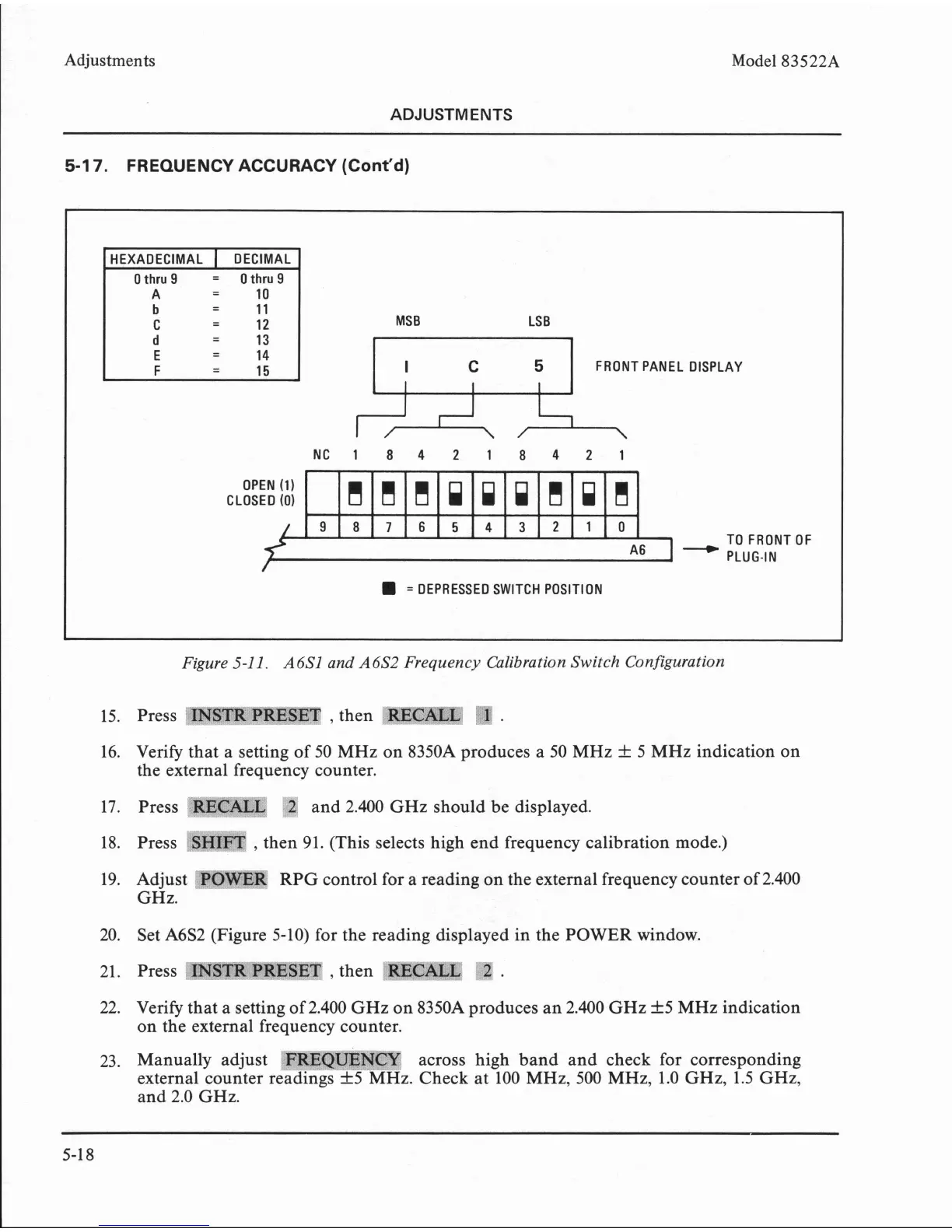
Figure 5-1
1.
A6Sl and A6S2 Frequency Calibration Switch Configuration
MSB LS
B
FRONT PANEL DISPLAY
Y
NC184218421
15. Press
mm
mEm
,
then
Rr'C;mr
"l"
.
OPEN (1)
CLOSED
(0)
16. Verify that a setting of 50
MHz
on 8350A produces a 50
MHz
f
5
MHz
indication on
the external frequency counter.
17. Press
*
'T
and 2.400
GHz
should be displayed.
TO FRONT OF
PLUG-IN
=
DEPRESSED SWITCH POSITION
9876543210
:y-=3r5
w4tl#i*
18. Press
SH~'FT
,
then 91. (This selects high end frequency calibration mode.)
19. Adjust
RPG
control for a reading on the external frequency counter of 2.400
GHz.
!!!uoCI!i!
20. Set A6S2 (Figure 5-10) for the reading displayed in the POWER window.
C
,
21. Press
MSm
'PRESET
,
then
RECALL'
2
.
22. Verify that a setting of 2.400
GHz
on 8350A produces an 2.400
GHz
f
5
MHz
indication
on the external frequency counter.
23. Manually adjust across high band and check for corresponding
external counter r
z.
Check at 100
MHz,
500
MHz,
1.0
GHz,
1.5
GHz,
and 2.0
GHz.