Adjustments Model 83522A
ADJUSTMENTS
5-1
8.
DELAY COMPENSATION (Cont'd)
PROCEDURE:
NOTE
This procedure assumes that
A3S1
is set to the factory-set position (Table
5-6).
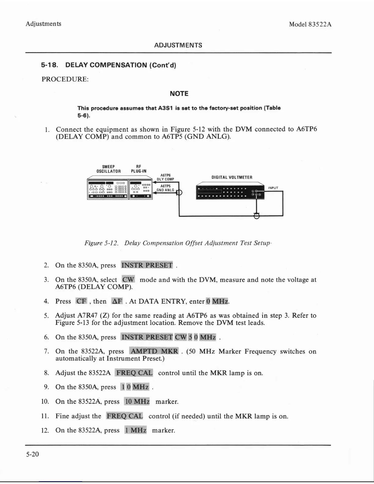
1. Connect the equipment as shown in Figure 5-12 with the DVM connected to A6TP6
(DELAY COMP) and common to A6TP5 (GND
ANLG).
SWEEP R
F
OSCILLATOR PLUG-IN
A6TP6
7
DLY
COMP
DIGITAL VOLTMETER
Figure
5-12.
Delay Compensation Offset Adjustment Test Setup-
2. On the 83504 press
~"RFTR~REY~T
.
r%-2vw=
3.
On the
83504 select
CW
mode and with the DVM, measure and note the voltage at
A6TP6 (DELAY COMP).
4. Press
wm
,
then
'XF
.
At DATA ENTRY, enters
5. Adjust
A7R47
(Z)
for the same reading at A6TP6 as was obtained in step 3. Refer to
Figure 5-13 for the adjustment location. Remove the DVM test leads.
6.
On
the
8350G
press
~~~~~~$m~~~~~
%ewQ
7j
7.
On the 835224 press
wmP"%Twm
.
(50 MHz Marker Frequency switches on
automatically at Instrument Preset.)
8. Adjust the
83522A
FRBQFE
control until the MKR lamp is on.
6%-
?**-
?
eZY.b
f
'*##a
9.
On the 83504 press
1
0
MHZ
.
10. On the 835224 press
f6-m~
marker.
11. Fine adjust the
'~~dW~~~
control (if needed) until the MKR lamp is on.
,
r*,
iw--*
r
r.-$.-my<
12. On the 835224 press
1
MHz
marker.