Model 83522A
ADJUSTMENTS
Adjustments
5-1
8.
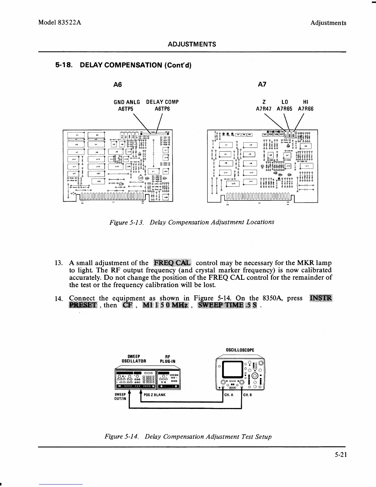
DELAY COMPENSATION (Cont'd)
GND ANLG DELAY COMP
A6TP5 A6TP6
Figure 5-1
3.
Delay Compensation Adjustment Locations
13.
A
small adjustment of the control may be necessary for the
MKR
lamp
to light. The
RF
output fr
crystal marker frequency) is now calibrated
accurately. Do not change the position of the
FREQ
CAL
control for the remainder of
the test or the frequency calibration will be lost.
14. the equi ment as sho
83504 press
then
&
,
M1aC5#
OSCILLOSCOPE
SWEEP
R F
OSCILLATOR PLUG-IN
Figure 5-1
4.
Delay Compensation Adjustment Test Setup
SWEEP POS
Z
BLANK
0
UTll
N
CH.
A
CH.
B