Adjustments
Model
83522A
ADJUSTMENTS
5-1
8.
DELAY COMPENSATION (Confd)
15. On the 83522A, ensure that the power is set to +13 dBm and press
16. Set the oscilloscope controls as follows:
Display Mode
....................................................
A vs.B
Display.
......................................................
MAG
X10
Ch. A Vertical Sensitivity.
........................................
2V/DIV
Ch. B Vertical Sensitivity..
.......................................
lV/DIV
Adjust the HOIZONTAL POSITION control to set the start of sweep exactly on the
leftmost graticule.
NOTE
Although the
HP
1740A is the specified oscilloscope, the use of an
oscilloscope with a variable persistance screen may be advantageous in
order to more clearly see the 50
MHz
markers when the sweep speed is
decreased to
10
milliseconds.
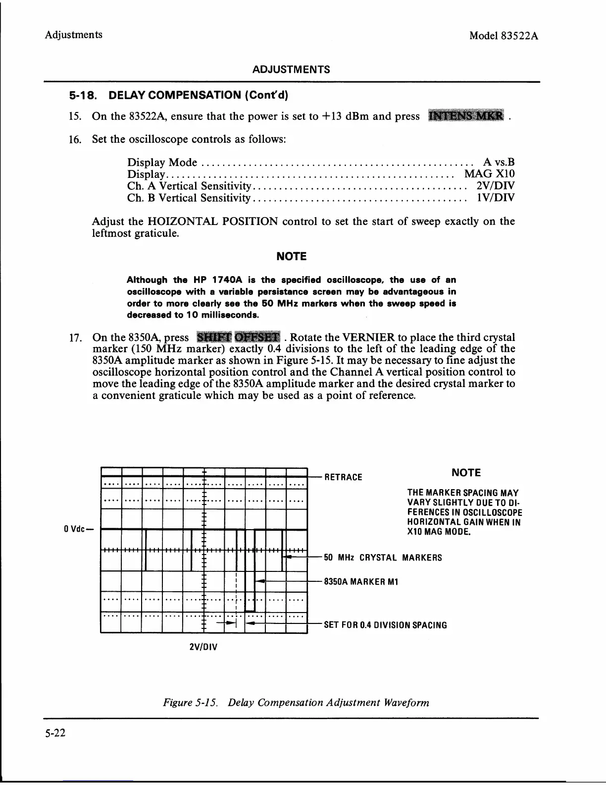
17.
On the 83504 press
.
Rotate the VERNIER to place the third crystal
marker (150
MHz
marker) exactly 0.4 divisions to the left of the leading edge of the
8350A amplitude marker as shown in Figure 5-15. It may be necessary to fine adjust the
oscilloscope horizontal position control and the Channel A vertical position control to
move the leading edge of the
8350A amplitude marker and the desired crystal marker to
a convenient graticule which may be used as a point of reference.
0
Vdc-
-
RETRACE
NOTE
THE MARKER SPACING MAY
VARY SLIGHTLY DUE TO
DI-
FERENCES IN OSCILLOSCOPE
HORIZONTAL
GAIN WHEN IN
XI0 MAG MODE.
-50 MHz CRYSTAL MARKERS
8350A MARKER MI
=SET FOR 0.4 DIVISION SPACING
2
Figure
5-1
5.
Delay Compensation Adjustment
Wave
form