Adjustments
ADJUSTMENTS
Model
83522A
5-20.
ALC
ADJUSTMENT
(Cont'd)
PROCEDURE:
NOTE
Turn
AC
power OFF when removing or installing
PC
boards.
NOTE
This procedure assumes that A3S1 is set to the factory-set position (Table
5-6), and at the
8350A Sweep Oscillator, 27.8
kHz
square wave modulation
is selected.
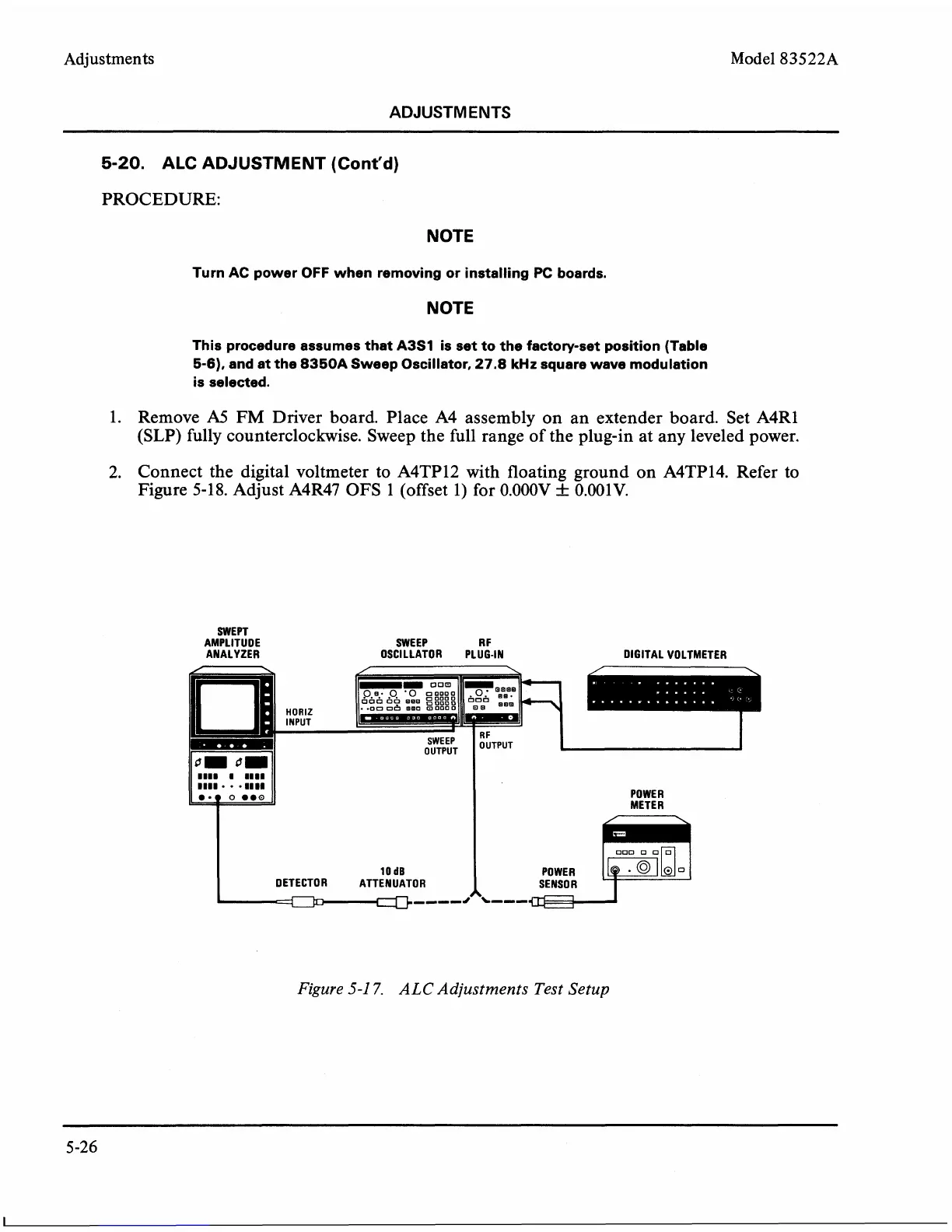
1. Remove
A5
FM
Driver board. Place A4 assembly on an extender board. Set A4R1
(SLP) fully counterclockwise. Sweep the full range of the plug-in at any leveled power.
2. Connect the digital voltmeter to
A4TP12 with floating ground on A4TP14. Refer to
Figure 5-18. Adjust
A4R47 OFS 1 (offset 1) for 0.000V
f
0.001V.
SWEPT
AMPLITUDE SWEEP
R
F
ANALYZER OSCILLATOR PLUG-IN DIGITAL VOLTMETER
POWER
Figure
5-1
7.
ALC Adjustments Test Setup