Model 83522A Adjustments
ADJUSTMENTS
5-20.
ALC ADJUSTMENT (Cont'd)
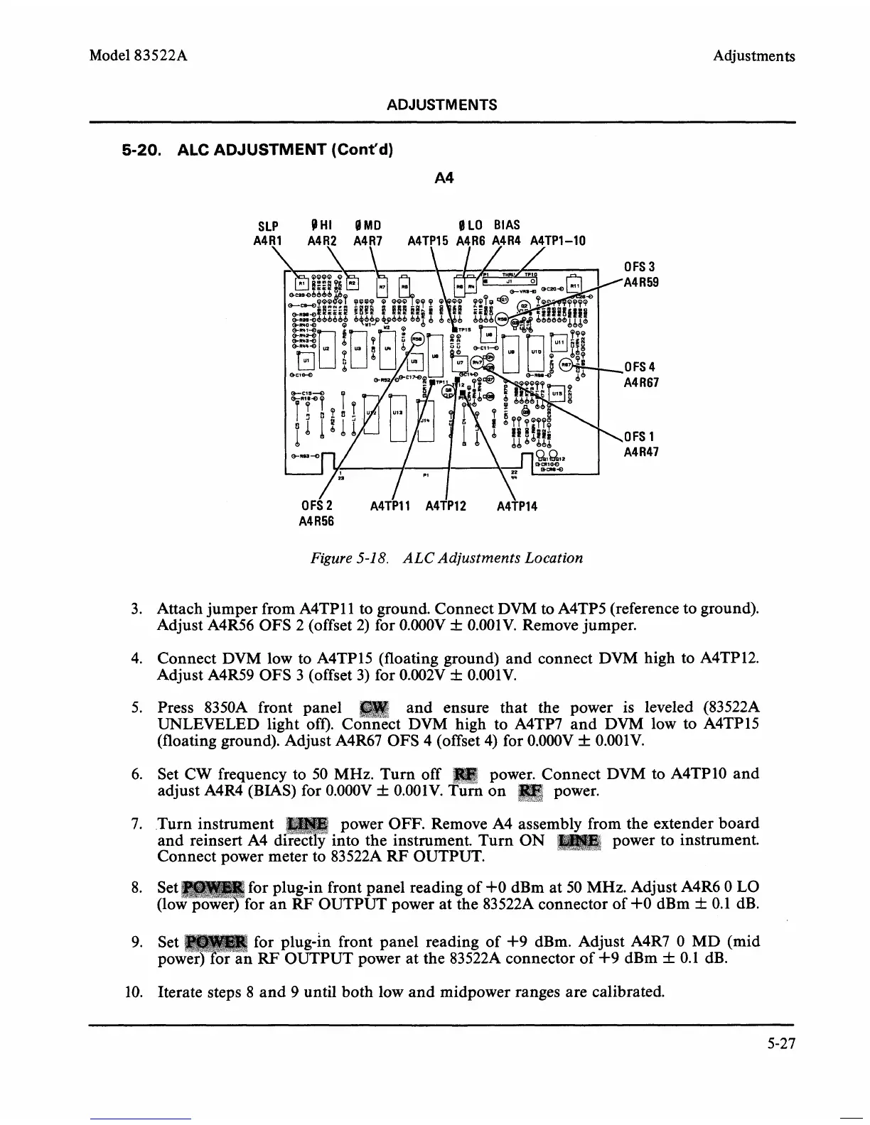
Figure
5-1
8.
ALC Adjustments Location
3. Attach jumper from A4TPll to ground. Connect DVM to A4TP5 (reference to ground).
Adjust
A4R56 OFS 2 (offset 2) for 0.000V
f
0.001V. Remove jumper.
4. Connect
DVM
low to A4TP15 (floating ground) and connect DVM high to A4TP12.
Adjust A4R59 OFS 3 (offset 3) for 0.002V
f
0.001V.
5.
Press 8350A front panel and ensure that the power is leveled (83522A
UNLEVELED
light off). ~onnzct DVM high to A4TP7 and DVM low to A4TP15
(floating ground). Adjust A4R67 OFS 4 (offset
4)
for 0.000V
f
0.001V.
6. Set
CW
frequency to 50 MHz. Turn off power. Connect DVM to A4TP10 and
adjust A4R4 (BIAS) for 0.000V
+
0.001V.
TuA
on
power.
7. .Turn instrument power OFF. Remove A4 asse
m
the extender board
and reinsert A4 d into the instrument. Turn ON
power to instrument.
Connect power meter to
83522A RF OUTPUT.
for plug-in front panel reading of
+O
dBm at 50
MHz.
Adjust A4R6 0 LO
for an RF OUTPUT power at the
83522A connector of
+O
dBm
f
0.1 dB.
for
plug-in front panel reading of +9 dBm. Adjust A4R7 0 MD (mid
RF
OUTPUT power at the 83522A connector of 4-9 dBm
f
0.1 dB.
10. Iterate steps
8
and
9
until both low and midpower ranges are calibrated.