Model 83522A
Adjustments
ADJUSTMENTS
5-27.
MARKER AND SAMPLER ADJUSTMENTS
(Cont'd)
Figure 5-34. Marker Envelope
Figure 5-35. 50
MHz
Birdie
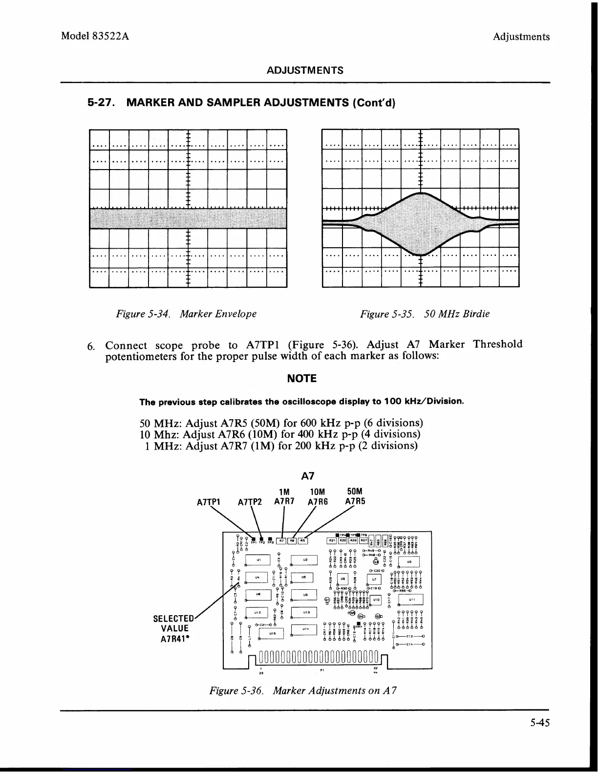
6. Connect scope probe to A7TP1 (Figure 5-36). Adjust A7 Marker Threshold
potentiometers for the proper pulse width of each marker as follows:
NOTE
The previous step calibrates the oscilloscope display to
100
kHz/Division.
50 MHz: Adjust A7R5 (50M) for 600 kHz p-p (6 divisions)
10 Mhz: Adjust
A7R6 (10M) for 400
kHz
p-p (4 divisions)
1
MHz: Adjust A7R7 (1M) for 200 kHz p-p (2 divisions)
SELECTED
VALUE
A7R41e
Figure 5-36. Marker Adjustments on
A 7