Adjustments
Model
83522A
ADJUSTMENTS
5-28.
EXTERNAL MARKER ADJUSTMENT
(Cont'd)
2. For best external marker operation, set the 8350A to the minimum required sweep
width and sweep speed. Select
8350A
0
WM~D:.
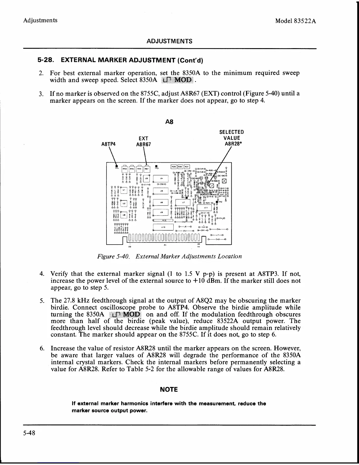
3. If no marker is observed on the 8755C, adjust A8R67 (EXT) control (Figure 5-40) until a
marker appears on the screen. If the marker does not appear, go to step 4.
EXT
SELECTED
VALUE
Figure
5-40.
External Marker Adjustments Location
4. Verify that the external marker signal (1 to 1.5 V p-p) is present at A8TP3. If not,
increase the power level of the external source to
+lo dBm. If the marker still does not
appear, go to step 5.
5.
The 27.8 kHz feedthrough signal at the output of A8Q2 may be obscuring the marker
birdie. Connect oscilloscope probe to
A8TP4. Observe the birdie amplitude while
turning the
8350A on and off. If the modulation feedthrough obscures
more than half o e (peak value), reduce
83522A output power. The
feedthrough level should decrease while the birdie amplitude should remain relatively
constant. The marker should appear on the
8755C. If it does not, go to step
6.
6.
Increase the value of resistor A8R28 until the marker appears on the screen. However,
be aware that larger values of
A8R28 will degrade the performance of the 8350A
internal crystal markers. Check the internal markers before permanently selecting a
value for
A8R28. Refer to Table 5-2 for the allowable range of values for A8R28.
NOTE
If external marker harmonics interfere with the measurement, reduce the
marker source output power.