MODEL 8559A
ADJUSTMENTS
ADJUSTMENTS
5
-
21.
BANDWIDTH FILTER ADJUSTMENTS
(Cont'd)
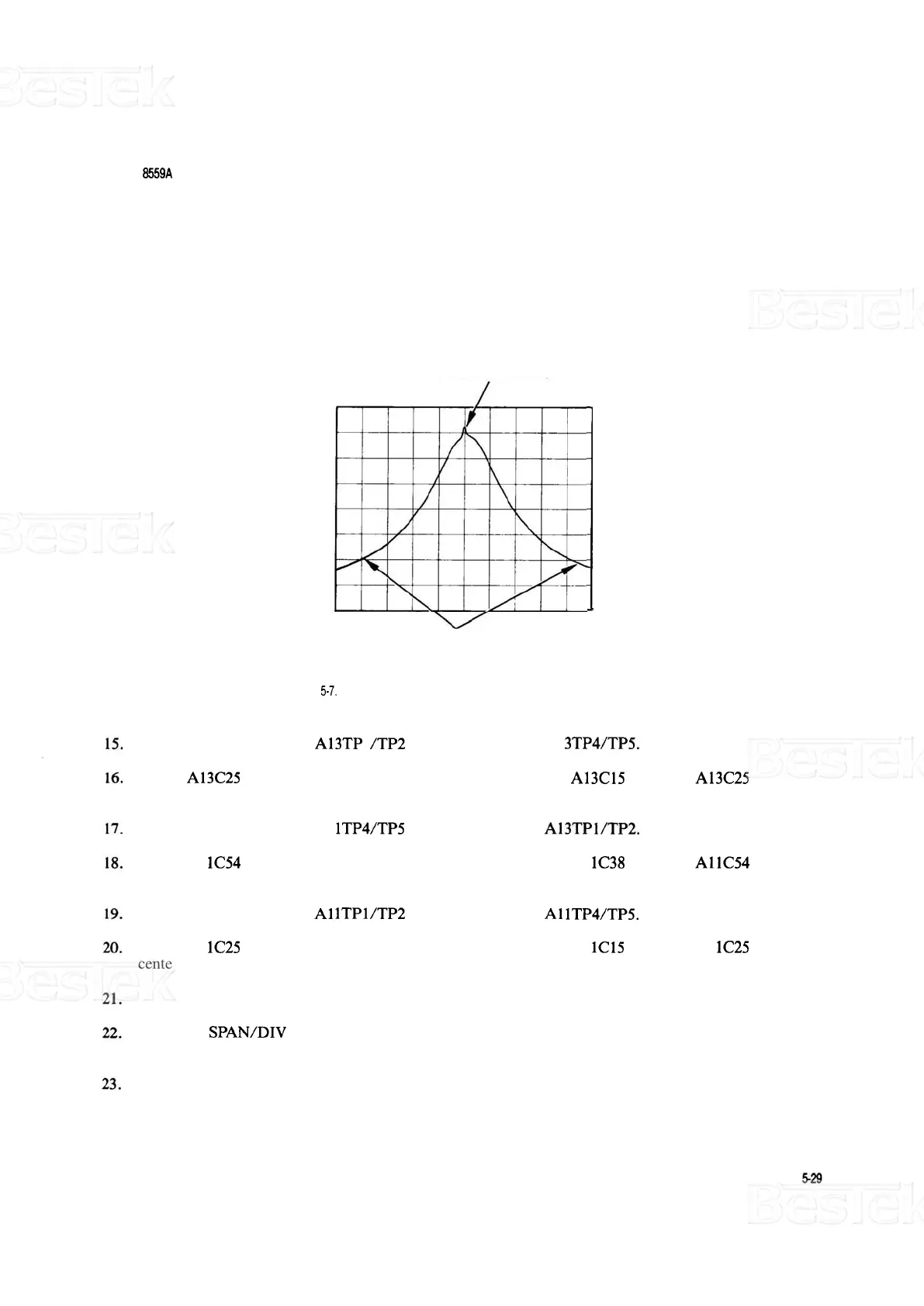
CHECK CENTERING
HERE (SPIKE IS
CRYSTAL RINGING)
CHECK SYMMETRY
HERE
(LOW
ON SKIRTS)
FIGURE
5-7.
ADJUSTING CRYSTAL SYMMETRY AND CRYSTAL CENTERING
Remove crystal short from A13TP 1 /TP2 and connect it across A1 3TP4/TP5.
Adjust A13C25 CTR for minimum signal amplitude. Then adjust A13C15 SYM and A13C25 CTR for a
centered and symmetrical bandpass.
Remove crystal short from A1
lTP4/TP5 and connect it across A13TPl/TP2.
Adjust A1 1C54 CTR for minimum signal amplitude. Then adjust A1 1C38 SYM and AllC54 CTR for a
centered and symmetrical bandpass.
Remove crystal short from
A1 lTPl/TP2 and connect it across A1 lTP4/TP5.
Adjust A1 1C25 CTR for minimum signal amplitude. Then adjust A1 1C15 SYM and A1 1C25 CTR for a
centered and symmetrical bandpass.
Remove the crystal shorts.
Set FREQ
SPAN/DIV to 10 kHz and RESOLUTION BW to 30 kHz. Center signal on CRT with TUN
-
ING control.
Switch RESOLUTION BW from 30 kHz to 10 kHz and back several times. Verify that signal shift does
not exceed 3 kHz (0.3 divisions). If signal shift is out of tolerance, return to step 11.