Chapter 3 173
Assembly Replacement
Procedure 5. A2, A3, A4, and A5 Assemblies
that the coaxial cables are routed properly on the clip as illustrated
in Figure 3-12 on page 175 for EC-series instruments, and in Figure
3-13 on page 176 for E-series instruments.
6. Lay the A2, A3, A4, and A5 assemblies flat against each other in the
folded-out position. Make sure that no cables become pinched
between the two assemblies.
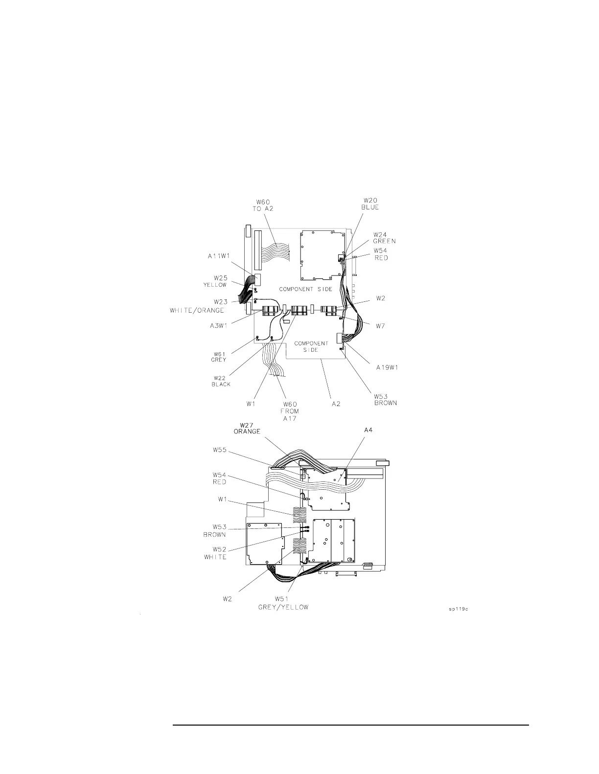
Figure 3-9 Assembly Cables (1 of 3) − EC-Series