Chapter 3 195
Assembly Replacement
Procedure 8. A7 through A13 Assemblies
deck using the three screws removed in step 3 under "Removal."
5. Torque the semi-rigid cables to 113 Ncm (10 in-lb).
6. Connect W14 and W16 to the A10 tracking generator.
A11 YTO
Removal
1. If the spectrum analyzer is an Option 002, remove the A10 tracking
generator before proceeding.
2. Place the spectrum analyzer top-side-down on the workbench.
3. Use a 5/16-inch wrench to remove W56/FL2/W57 (as a unit).
4. Disconnect W38 at the A11 assembly.
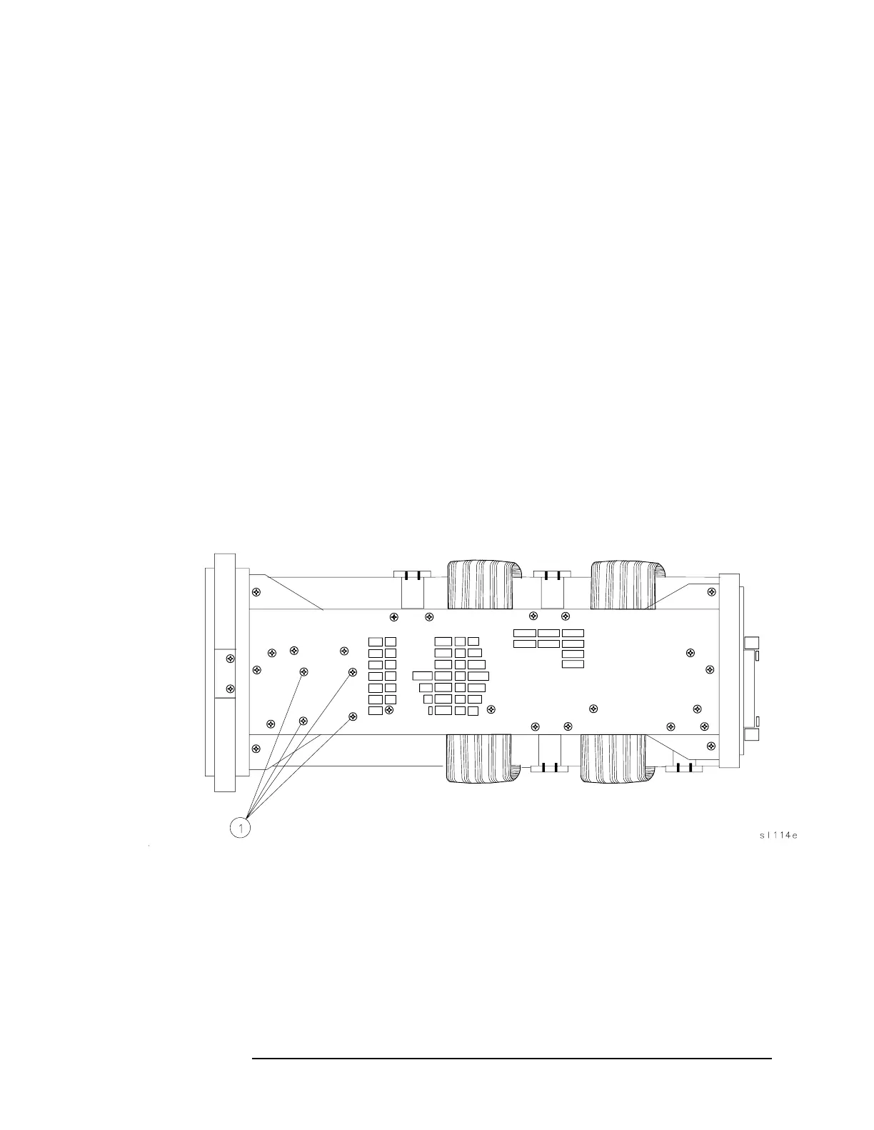
5. Remove the A11 mounting screws (1) shown in Figure 3-24 on page
195.
6. Disconnect W10 from A11.
Figure 3-24 A11 Mounting Screws
Replacement
1. Reconnect W10 to A11.
2. Place the A11 assembly in the spectrum analyzer.
3. Secure the A11 assembly to the right side frame using the four
screws (1) removed in step 5 under "Removal."